
Specifications


i50 Manual (5.10)
Page 10
© 2015 Datalink Systems, Inc.
www.datalinksystemsinc.com
4.3 Program Connector
The i50 Program connector is used to update the unit’s firmware and adjust settings. It may also be
used to access the i50 COM1 port (see section 4.5.4). Firmware can be updated by connecting a PC
to the Program port and running the firmware update utility.
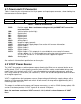
Table 2 shows the pin assignment of the Program connector, including the connections required to
attach a female DB-9 connector. Pin 1 is located on the right side looking into the connector on the
front panel. All pins (except VOUT and GND) use RS-232 voltage levels.
RJ-45 Pin
Pin Name
Direction (relative to i50)
DB-9 Pin (female)
1
VOUT
Output
-
2
MODE
Input
7 (RTS)
3
RX
Input
3 (TX)
4
STATUS
Output
6 (DSR)
5
TX
Output
2 (RX)
6
RESET
Input
4 (DTR)
7
Not used
-
-
8
GND
-
5 (GND)
Table 2 – Program Connector
VOUT: Switched power output. See section 4.2 for more information
MODE: Used to enter firmware programming mode. Turn off (low) for normal use
RX: Data input
STATUS: Indicates CPU mode
TX: Data output
RESET: Used to reset CPU. Must be turned off (low) for normal operation
GND: Ground
Note: this pin layout has been chosen so that a Datalink Mobile Data Terminal (MDT) can be plugged
in using a standard RJ-45 to RJ-45 LAN cable. The MDT provides an LCD screen and keypad for
applications where an advanced user interface is required.