PowerScan® RF Handheld Bar Code Scanner User’s Guide
Datalogic Scanning, Inc. 959 Terry Street Eugene, Oregon 97402 Telephone: (541) 683-5700 Fax: (541) 345-7140 An Unpublished Work - All rights reserved. No part of the contents of this documentation or the procedures described therein may be reproduced or transmitted in any form or by any means without prior written permission of Datalogic Scanning, Inc. or its subsidiaries or affiliates ("Datalogic" or “Datalogic Scanning”).
Datalogic Scanning, Inc. POWERSCAN® END USER LICENSE AGREEMENT Notice to End User: The Datalogic Product you have acquired contains embedded Software, which is integral to the product’s operation. This Software is being provided to you under license, subject to the terms and conditions of this Agreement. If you use the Datalogic Product, you will be deemed to have accepted the terms and conditions of this Agreement.
6.2 warranty period, Datalogic’s liability is limited to providing End User with one copy of corrections or responding to End User's problem reports according to Datalogic's standard assistance practices. Datalogic does not warrant that the product will meet End User's requirements or that use of the product will be uninterrupted or error free, or that Datalogic's remedial efforts will correct any nonconformance.
Standard Warranty Datalogic warrants to Customer that Datalogic's products will be free from defects in materials and workmanship for a period of three years from product shipment. In order to obtain service under this Warranty, Customer must notify Datalogic of the claimed defect before the expiration of the Warranty period and obtain from Datalogic a return authorization number for return of the product to designated Datalogic service center.
NOTES User’s Guide iv
TABLE OF CONTENTS Unpack and Inspect Your Scanner ................................................................................1 References ....................................................................................................................1 Quick Start Instructions .................................................................................................1 Using the PowerScan RF System .................................................................................8 How to Scan ..
vi PowerScan® RF Scanner
Unpack and Inspect Your Scanner After unpacking your new scanner, check the contents of the shipping carton to ensure all the items you ordered are included: • • • • PowerScan® RF handheld scanner Battery Pack(s) User’s Guide (this manual) Optional Accessories that you ordered. (The scanner can be purchased with or without accessory kits.) If your package contains wrong or missing components, contact your place of purchase. If there are damaged components, immediately file a claim with the carrier.
Installing the Battery To assure maximum usage, batteries should always be fully charged before their initial use. (See “Battery Charging and Maintenance” on page 8.) NOTE Orient the battery as shown in Figure 1, then push it into the scanner until it snaps in place. To remove the battery, push in on the release tabs on both sides of the battery’s base and pull it straight out of the scanner. Figure 1. Installing the Battery 1 1.
Verifying Once a charged battery has been installed in the scanner, scan the samScanner ple bar codes in the back of this manual that correspond to the symbolOperation ogies your scanner is programmed to read. If unsure how to do this, see the section on How to Scan in this manual. The system may signal with one or a combination of indicators depending upon how the scanner and Base Station are programmed to respond (see LED and Beeper Indications for details).
Figure 2. Connecting/Disconnecting the Interface (I/F) Cable a b c 2. Consult your Host Terminal manual to determine the required communication parameters for the Host Terminal (e.g., baud rate, parity, etc.) and, if necessary, modify the programmed parameters to be compatible with those requirements.
The Base Station’s POWER LED should be illuminated when the unit is properly connected to power. Figure 3. Connecting Power to the Base Station 5. Apply power to the Host Terminal. 6. Verify communication with the Host Terminal by aiming the linked scanner at a sample bar code from the back pages of this manual, and pulling the trigger (see How to Scan for tips about scanning bar codes). Confirm that the scanner/Base Station sent the data to the host terminal. If not, see the section, Troubleshooting.
The existing Base Station system configuration can be automatically downloaded to the scanner. This automatic download feature is configurable and can be disabled. See the Systems Manual for more information about this feature. If downloading occurs, a slight delay with link verification announcement will occur.
Verifying Scanner-toBase Station Communications Point the linked scanner at a sample bar code from the back pages of this manual, and pull the trigger (see How to Scan for tips on scanning bar codes). Watch the TX/RX (transmit/receive) indicator LED on the Base Station and/or scanner green LED while scanning the bar code. The LEDs should flash momentarily as the two devices communicate. If no communication is indicated, refer to the troubleshooting section of the Systems Manual.
Using the PowerScan RF System This section covers the following topics: • Battery Charging and Maintenance • How to Scan • LED and Beeper Indications Battery Charging and Maintenance NOTE When the scanner is in use, a low battery condition is indicated by a repeated two-flash signal from the scanner’s green LED every time the trigger is pulled before the laser is enabled. This indicator may have been disabled via custom programming. See LED and Beeper Indications for more information.
Rapid flashing indicates that charging is taking place. Rapid charging occurs when the battery temperature is between 10°C (50°F) and 46°C (115°F), and/or voltage of the battery is between 2.0 and 3.2V. Charge time is less than 4.2 hours. Rapid charge ends with the battery at approximately 90 to 95% capacity. The CHARGE LED remains on steady when trickle charging or after the charge cycle is complete. A scanner may be charged simultaneously while other scanners are in use with the Base Station.
Disposing of There presently are no US, North America or World disposal requireBatteries ments for NiMH batteries, so when they won't hold a charge anymore, the batteries can be disposed of, preferably through a recycling center. Four Station If you have a Four Station Charger, batteries are inserted for charging Charger as shown in Figure 5. A 90% rapid charge can be achieved in only two hours when using this optional accessory, half the time than when a Base Station is used for charging.
How to Scan Figure 6 illustrates some tips to help get the best scanning results: 1. The scanner must be pointed at a slight angle to the bar code. Do not hold the scanner perpendicular to the bar code. 2. The laser beam must cross the entire bar code. The scanner cannot correctly read if the entire bar code is not scanned. Figure 6.
Depth of Field There are currently four different range models for the scanner. Depending upon the model type of your scanner, you’ll need to hold the unit at a given distance from the bar code to achieve optimum scanning results. The following diagrams provide depth of field information for each of the models when scanning grade A, Code 39 bar codes: Standard Range (SR), High Density (HD), Long Range (LR) and Extra Long Range (XLR). Definition of a "mil" A "mil" is equal to 0.001 inches.
See the section titled, Definition of a "mil" for more information about reading this chart. Measurements are based on HD models set with the standard 28° scan width (as opposed to the Half Angle setting of 14°). Reference the Programming Manual for more information about the Half Angle feature. NOTE Specifications are subject to change without notice. Figure 8. Depth of Field (HD) Depth of Field FRONT OF SCANNER Paper Labels (HD decoded model, Code 39) 3 mil 4 mil 5 mil 7.
See the section titled, Definition of a "mil" for more information about reading this chart. Measurements are based on LR models set with the a 14° scan width (as opposed to the alternate Full Angle setting of 28°). Reference the Programming Manual for more information about the Half Angle feature. NOTE Specifications are subject to change without notice. Figure 9. Depth of Field (LR) Depth of Field FRONT OF SCANNER Paper Labels (LR decoded model, Code 39) 7.
See the section titled, Definition of a "mil" for more information about reading this chart. Measurements are based on XLR models set with a 10° scan angle width. NOTE Specifications are subject to change without notice. Figure 10.
LED and Beeper Indications The Base Station LED indicators and the scanner’s LEDs and beeper are used to announce system status and perform other useful signals. The tables below list the default function of each of the various indicators. Some LED and beeper indications can be disabled or modified via scanner programming. The tables indicate the default behavior of the indicators, with shaded rows representing features that are programmable. NOTE Table 1.
Table 2. Scanner YELLOW LED Functions LED INDICATION Laser on indication DURATION On Steady COMMENT The yellow LED illuminates whenever the laser is on. Table 3. Scanner BEEPER Functions SPEAKER INDICATION Scanner Not Currently Linked DURATION Six beeps consisting of 20 ms on, 20 ms off COMMENT Indicates a bar code was read before the scanner was linked to a Base Station.
SPEAKER INDICATION Transmission Error Beep DURATION High, then low, then high, then low. Indicates unsuccessful transmission to the host. Low, then medium, then high. Indicates a scanner has been successfully linked to a base station. High, then medium, then low. Indicates a scanner has been successfully unlinked from a base station. Varies. Consists of a long tone followed by multiple short tones. Enables service technicians to identify Field Replaceable Unit (FRU) errors.
LED INDICATION DURATION Continuous flashing Charge (Battery) Power COMMENT When a scanner is nested in the station, this indicates its battery is being quick charged. Lit Constantly When a scanner is nested in the station, this indicates its battery is at or near full charge. Not Lit A scanner is not present or incorrectly inserted into the station. It can also mean the battery is below 0°C (too cold for charge) Lit Constantly Indicates that power is on. a.
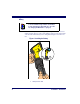
Enhanced Scanning for Hard-to-Read Bar Codes Decoded scanners can be programmed to decode extremely poor quality bar codes by activating advanced Quadralogic II™ Decoding. To select this feature, see the Programming Guide. Scanner programming can also be performed using your PC and the Configurator Express™ On-Screen Programming Kit. Information about manuals, kits and programming software for this product are available at our website. See the back cover for our web address. NOTE Figure 11.
NOTE Figure 11 above shows label placement ONLY. For actual regulatory, patent and other applicable information, view the labels on the product itself, or call your nearest sales or service representative. Laser Cautions The PowerScan RF bar code scanner is certified in the U.S. to conform to the requirements of DHHS/CDRH 21CFR Subchapter J for Class II laser products (SR and LR) and Class IIIa (XLR). Class II and IIIa products are not considered to be hazardous.
Radio Frequency Interference This device complies with Part 15 of the FCC Rules. Operation is subject to the following two conditions: 1. This device may not cause harmful interference, and 2. This device must accept any interference received, including interference that may cause undesired operation. This Class A digital apparatus complies with Canadian ICES-003. Cet appareil numérique de la classe A est conforme à la norme NMB003 du Canada.
Maintenance The scan window will require occasional cleaning to remove smudges, dust and other debris. To ensure optimal performance, clean the Scan Window using a soft cloth or lens tissue dampened with isopropyl alcohol (or equivalent). See Figure 12. The scanner body can also be cleaned using this method. Figure 12.
Troubleshooting Troubleshoot your RF scanning system by performing the following checks: For the RF system, ensure that... • the battery is charged. See “Battery Charging and Maintenance” on page 8. • the battery is properly installed. See “Installing the Battery” on page 2. • the scanner is linked to the desired Base Station. See “Linking the Scanner to a Base Station” on page 5.
Sample Bar Codes Use these test bar codes to check the scanner’s ability to read the various symbologies represented. Code 128 C o d e 1 2 8 . T e s t Code 39 C O D E 3 9 . T E S T Interleaved 2 of 5 0 1 2 3 4 5 6 7 8 9 Standard 2 of 5 1 2 3 4 5 6 7 8 9 0 Codabar A $ 9 9 . 9 5 A Code 93 Co d e User’s Guide 9 3 .
MSI/Plessey 4 14476925 UPC-A 00112 23344 0 0 4 9 UPC-A with 2 digit Add-on 0 60992 01118 7 6 9 0 0 0 UPC-A with 5 digit Add-on 0 08029 51041 8 UPC-E 0 998875 0 EAN-8 0021 0126 EAN-13 1 101234 567891 26 PowerScan® RF Scanner
DECLARATION OF CONFORMITY Datalogic hereby declares that the Equipment specified below has been tested and found compliant to the following Directives and Standards: Directives: EMC 89/336/EEC Low Voltage 73/23/EEC R&TTE 1999/5/EC Standards: EN 300 683:1997 - Radio EN 300 220-3:2000 - Radio Immunity EN 60950:2000 - ITE Safety EN 60825-1/A2:2001 - Laser Safety Equipment Type: Product Model Name: Placed into EU Service: Serial No.
Australia Japan Datalogic Scanning Pty Ltd Datalogic Scanning KK North Ryde, Australia Shinagawa, Tokyo, Japan Telephone: [61] (2) 9870 3200 Telephone: 81 (0)3 3491 6761 Fax: [61] (2) 9878 8688 Fax: 81 (0)3 3491 6656 France and Benelux Latin America Datalogic Scanning Sarl Datalogic Scanning, Inc LES ULIS Cedex, France Miami, Florida, USA Telephone: [33].01.64.86.71.00 Telephone: (305) 591-3222 Fax: [33].01.64 46.72.