C-BOX 200 Installation Manual
C-BOX 200 INSTALLATION MANUAL
DATALOGIC S.p.A.
CONTENTS GUIDE TO INSTALLATION.............................................................. iv SAFETY PRECAUTIONS .................................................................vii Power Supply ....................................................................................vii 1 1.1 GENERAL FEATURES...................................................................... 1 Description ......................................................................................... 1 2 2.1 2.2 2.3 2.4 2.4.
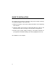
GUIDE TO INSTALLATION The following can be used as a checklist to verify all of the steps necessary for complete installation of the C-BOX 200. 1) Read all information in the section "Safety Precautions" at the beginning of this manual. 2) Correctly position and mount the C-BOX 200 within the reach of the barcode scanner cable, according to the information in paragraph 2.3.
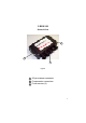
C-BOX 200 General View 3 1 2 Figure A 1 25-pin scanner connector 2 Compression connectors 3 Cover screws (4) v
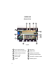
C-BOX 200 General View 7 8 9 12 4 5 10 3 11 1 2 6 Figure B 1 Power switch (ON/OFF) vi 2 Spring clamp terminal blocks 7 GET button 8 SEND button 3 Multidrop address switches 9 Auxiliary port connector 4 Power on LED 10 Chassis grounding selector 5 Warning LED 11 Termination resistance switch 6 Tx LED 12 OM4000 jumpers
SAFETY PRECAUTIONS POWER SUPPLY ATTENTION: READ THIS INFORMATION BEFORE INSTALLING THE PRODUCT - This product is intended to be installed by Qualified Personnel only. The C-BOX 200 is intended to be supplied by an NEC Class 2 power source, rated 10-30 V, minimum 0.65 A. See par. 2.4.1 for correct power supply connections.
viii
DATALOGIC C-BOX 200 1 GENERAL FEATURES 1.1 DESCRIPTION The C-BOX 200 is a connection box which can be used as an accessory of the Datalogic scanners to perform the following functions: • Facilitate the connection of the scanner signals using a spring clamp connector. • Perform a conversion from RS232 to RS485 multidrop system to connect a RS232 scanner to a multidrop network. • Optocoupled RS485 interface is used over long distances or in electrically noisy environments.
C-BOX 200 DATALOGIC 2 INSTALLATION 2.1 PACKAGE CONTENTS Verify that the C-BOX 200 and all the parts supplied with the equipment are present and intact when opening the packaging; the list of parts includes: 1) C-BOX 200 2) Installation manual 2 1 Figure 2.
DATALOGIC C-BOX 200 2.2 OPENING THE DEVICE To install the C-BOX 200 or during normal maintenance, it is necessary to open it by unscrewing the four cover screws: WARNING The C-BOX 200 must be disconnected from the power supply during this operation. Figure 2.2 - Opening the C-BOX 200 It is possible to perform the following operations: • Proceed with the cable connections (see paragraph 2.4.2). • Set the multiplexer address selection on the rotary switches. • Mount the C-BOX 200 to a wall or panel.
C-BOX 200 DATALOGIC 2.3 MECHANICAL INSTALLATION The diagram below gives the overall dimensions of the C-BOX 200 and may be used for its installation. ∅ ∅ mm in Figure 2.
DATALOGIC C-BOX 200 C-BOX 200 can be installed to operate in different positions. The two screw holes inside the housing of the C-BOX 200 are for mechanical fixture (Figure 2.4). To mount the C-BOX 200: 1) Open the C-BOX 200 by unscrewing the 4 cover screws. If necessary, using the two mounting holes inside the device as a pattern, mark the panel with an appropriate object and then drill two holes in the panel.
C-BOX 200 DATALOGIC 2.4 ELECTRICAL CONNECTIONS AND SETUP The following figure shows the typical layout. The dotted line in the figure refers to an optional hardware configuration. PC Scanner Auxiliary Interface SCANNER System Cables Figure 2.5 – System layout A PC can be quickly connected to the C-BOX 200 (and consequently to the scanner auxiliary interface) through the internal 9-pin connector.
DATALOGIC C-BOX 200 2.4.1 Power Supply Power is supplied to the C-BOX 200 through the pins provided on the spring clamp connector. The power switch (see Figure 2.6) switches the power supply ON or OFF for both the C-BOX 200 and the connected scanner. ON S1 OFF Figure 2.6 - Power switch ON/OFF positions USER INTERFACE C-BOX 1 VS 2 GND V+ (10 - 30 Vdc) GND Figure 2.
C-BOX 200 DATALOGIC 2.4.2 System Wiring The connection and wiring procedure for C-BOX 200 is described as follows: 1) Open the C-BOX 200 as described in paragraph 2.2. 2) Verify that the C-BOX 200 power switch is off (see Figure 2.6). 3) Unscrew the compression connectors and pass all the system cables through them into the C-BOX 200 housing. 4) To connect the power and input/output signals: • Prepare the individual wires of the system cables by stripping the insulation back approximately 1 cm.
DATALOGIC C-BOX 200 The C-BOX 200 spring clamp connector pinouts are indicated in the following table. Refer to the scanner Installation Manual for details.
C-BOX 200 DATALOGIC 2.4.3 Chassis Grounding Jumper Settings The scanner chassis grounding method can be selected by positioning a jumper (see Figure 2.9). In this way the scanner chassis can be connected to earth ground (only if pins 7 or 8 are connected to a good earth ground) or to the power supply ground signal. The scanner chassis can also be left floating but, in this case, the jumper must be removed. to EARTH GROUND (default) to GND floating Figure 2.
DATALOGIC C-BOX 200 2.4.4 Multidrop Address Selection For RS485 half-duplex interface connections, the scanner multidrop address should be set using the rotary switches placed inside the C-BOX 200. The valid address range is from 00 to 31. This value is read only at poweron; any change at run-time has no effect. If an invalid value is detected (32-99) the C-BOX cannot communicate with the Multiplexer and the green LED remains off.
C-BOX 200 DATALOGIC 2.4.5 RS485 Bus Termination ON OFF S2 Figure 2.11 - Termination resistance switch The switch S2 enables or disables the insertion of the bus termination resistor for RS485 Half Duplex Multidrop applications. CAUTION In Multiplexer applications the termination resistor must be enabled ONLY on the last device of the chain, the farthest away from the Multiplexer (assuming the Multiplexer is the first device of the chain).
DATALOGIC C-BOX 200 2.4.
C-BOX 200 DATALOGIC 2.4.7 OM4000 Jumper Settings J1 J2 Figure 2.13 - OM4000 jumpers The jumpers allow connection to the EXT TRIG signals on separate spring clamp terminals for applications which use the OM4000 Oscillating Mirror in Trigger Mode. They are used together and they have the following significance: when a jumper is in the J1 position (see Figure above) pin 40 is connected to pin 27 (EXT TRIG+); a jumper in J2 position connects pin 20 to pin 28 (EXT TRIG-).
DATALOGIC C-BOX 200 2.5 9-PIN SCANNER AUXILIARY SERIAL INTERFACE The scanner auxiliary serial interface available on the internal 9-pin connector can be used either for configuration through WinHost or for data monitoring. The details of the connector pins are indicated in the following table: Figure 2.14 - 9-pin male connector Pin 1 2 3 4 5 6 9 Name 9-pin connector pinout Function RXA TXA SGND N.C. Auxiliary RS232 Auxiliary RS232 N.C. Signal Ground N.C. N.C.
C-BOX 200 DATALOGIC 2.6 SCANNER REQUIREMENTS 1) The C-BOX 200 can be connected to the following scanners through the 25-pin connector illustrated in Figure A. DS2100 DS4300 DS2400 DS4600 It is necessary to use RS232 model (X0XX) for DS2100 and DS2400 scanner, while DS4300 and DS4600 RS232 interface must be selected by the user. 2) At least one Terminator Character should be enabled in the connected scanner (see the Terminator parameters in the Data Format section of the Help On Line).
DATALOGIC C-BOX 200 2.7.1 GET/SEND Buttons The C-BOX 200 has two internal function buttons (GET, SEND). The procedure to enable the GET/SEND function is the following: 1. Press both the buttons GET and SEND at the same time for at least one second; the warning LED is turned ON. 2. Release the buttons. GET 3. SEND Press the left button corresponding to the GET function or press the right button corresponding to the SEND function.
C-BOX 200 DATALOGIC 2.7.2 LED Indicators Power on Warning Tx Figure 2.15 - LED Indicators The three internal LEDs of the C-BOX 200 (see Figure 2.15) indicate the following: POWER ON (red) indicates the C-BOX 200 is connected to the power supply and the power switch is ON. WARNING (red) indicates a warning or error condition: it is ON when a connection procedure is in progress (the system is busy) or during a GET/SEND procedure. It blinks when an error condition occurs.
DATALOGIC C-BOX 200 3 TECHNICAL FEATURES ELECTRICAL FEATURES Power Supply voltage 10 to 30 Vdc Power consumption max. 1.4 W + scanner USER INTERFACE LED indicators Power ON, Warning, Tx (RS485 Multidrop activity) PHYSICAL FEATURES Mechanical dimensions Weight 167 x 115 x 40 mm (6.57 x 4.53 x 1.57 in.) about 340 g. (12 oz.