PowerScan® RF Handheld Bar Code Scanner Handstrichcodeleser Douchette Laser Lettore portatile di codici a barre SR/HD/LR/XLR User’s Guide Benutzerhandbuch Guide de L’utilisateur Manuale d’Istruzioni
Datalogic Scanning, Inc. 959 Terry Street Eugene, Oregon 97402 Telephone: (541) 683-5700 Fax: (541) 345-7140 An Unpublished Work - All rights reserved. No part of the contents of this documentation or the procedures described therein may be reproduced or transmitted in any form or by any means without prior written permission of Datalogic Scanning, Inc. or its subsidiaries or affiliates ("Datalogic" or “Datalogic Scanning”).
Datalogic Scanning, Inc. POWERSCAN® END USER LICENSE AGREEMENT Notice to End User: The Datalogic Product you have acquired contains embedded Software, which is integral to the product’s operation. This Software is being provided to you under license, subject to the terms and conditions of this Agreement. If you use the Datalogic Product, you will be deemed to have accepted the terms and conditions of this Agreement.
6.2 warranty period, Datalogic’s liability is limited to providing End User with one copy of corrections or responding to End User's problem reports according to Datalogic's standard assistance practices. Datalogic does not warrant that the product will meet End User's requirements or that use of the product will be uninterrupted or error free, or that Datalogic's remedial efforts will correct any nonconformance.
Standard Warranty Datalogic warrants to Customer that Datalogic's products will be free from defects in materials and workmanship for a period of three years from product shipment. In order to obtain service under this Warranty, Customer must notify Datalogic of the claimed defect before the expiration of the Warranty period and obtain from Datalogic a return authorization number for return of the product to designated Datalogic service center.
NOTES User’s Guide iv
MASTER CONTENTS Table of Contents ...........................................................................1 Deutsches Inhaltsverzeichnis .......................................................29 Français Sommaire ......................................................................59 Italiano Indice ...............................................................................
ii PowerScan® RF Scanner
TABLE OF CONTENTS Unpack and Inspect Your Scanner ................................................................................1 References ....................................................................................................................1 Quick Start Instructions .................................................................................................1 Installing the Battery ...............................................................................................
2 PowerScan® RF Scanner
Unpack and Inspect Your Scanner After unpacking your new scanner, check the contents of the shipping carton to ensure all the items you ordered are included: • • • • PowerScan® RF handheld scanner Battery Pack(s) User’s Guide (this manual) Optional Accessories that you ordered. (The scanner can be purchased with or without accessory kits.) If your package contains wrong or missing components, contact your place of purchase. If there are damaged components, immediately file a claim with the carrier.
Installing the Battery To assure maximum usage, batteries should always be fully charged before their initial use. (See “Battery Charging and Maintenance” on page 10.) NOTE Orient the battery as shown in Figure 1, then push it into the scanner until it snaps in place. To remove the battery, push in on the release tabs on both sides of the battery’s base and pull it straight out of the scanner. Figure 1. Installing the Battery 1 1.
Verifying Once a charged battery has been installed in the scanner, scan the samScanner ple bar codes in the back of this manual that correspond to the symbolOperation ogies your scanner is programmed to read. If unsure how to do this, see the section on How to Scan in this manual. The system may signal with one or a combination of indicators depending upon how the scanner and Base Station are programmed to respond (see LED and Beeper Indications for details).
Figure 2. Connecting/Disconnecting the Interface (I/F) Cable a b c 2. Consult your Host Terminal manual to determine the required communication parameters for the Host Terminal (e.g., baud rate, parity, etc.) and, if necessary, modify the programmed parameters to be compatible with those requirements.
The Base Station’s POWER LED should be illuminated when the unit is properly connected to power. Figure 3. Connecting Power to the Base Station 5. Apply power to the Host Terminal. 6. Verify communication with the Host Terminal by aiming the linked scanner at a sample bar code from the back pages of this manual, and pulling the trigger (see How to Scan for tips about scanning bar codes). Confirm that the scanner/Base Station sent the data to the host terminal. If not, see the section, Troubleshooting.
The existing Base Station system configuration can be automatically downloaded to the scanner. This automatic download feature is configurable and can be disabled. See the Systems Manual for more information about this feature. If downloading occurs, a slight delay with link verification announcement will occur.
Verifying Scanner-toBase Station Communications Point the linked scanner at a sample bar code from the back pages of this manual, and pull the trigger (see How to Scan for tips on scanning bar codes). Watch the TX/RX (transmit/receive) indicator LED on the Base Station and/or scanner green LED while scanning the bar code. The LEDs should flash momentarily as the two devices communicate. If no communication is indicated, refer to the troubleshooting section of the Systems Manual.
Using the PowerScan RF System This section covers the following topics: • Battery Charging and Maintenance • How to Scan • LED and Beeper Indications Battery Charging and Maintenance NOTE When the scanner is in use, a low battery condition is indicated by a repeated two-flash signal from the scanner’s green LED every time the trigger is pulled before the laser is enabled. This indicator may have been disabled via custom programming. See LED and Beeper Indications for more information.
Rapid flashing indicates that charging is taking place. Rapid charging occurs when the battery temperature is between 10°C (50°F) and 46°C (115°F), and/or voltage of the battery is between 2.0 and 3.2V. Charge time is less than 4.2 hours. Rapid charge ends with the battery at approximately 90 to 95% capacity. The CHARGE LED remains on steady when trickle charging or after the charge cycle is complete. A scanner may be charged simultaneously while other scanners are in use with the Base Station.
Disposing of There presently are no US, North America or World disposal requireBatteries ments for NiMH batteries, so when they won't hold a charge anymore, the batteries can be disposed of, preferably through a recycling center. Four Station If you have a Four Station Charger, batteries are inserted for charging Charger as shown in Figure 5. A 90% rapid charge can be achieved in only two hours when using this optional accessory, half the time than when a Base Station is used for charging.
How to Scan Figure 6 illustrates some tips to help get the best scanning results: 1. The scanner must be pointed at a slight angle to the bar code. Do not hold the scanner perpendicular to the bar code. 2. The laser beam must cross the entire bar code. The scanner cannot correctly read if the entire bar code is not scanned. Figure 6.
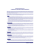
Depth of Field There are currently four different range models for the scanner. Depending upon the model type of your scanner, you’ll need to hold the unit at a given distance from the bar code to achieve optimum scanning results. The following diagrams provide depth of field information for each of the models when scanning grade A, Code 39 bar codes: Standard Range (SR), High Density (HD), Long Range (LR) and Extra Long Range (XLR). Definition of a "mil" A "mil" is equal to 0.001 inches.
See the section titled, Definition of a "mil" for more information about reading this chart. Measurements are based on HD models set with the standard 28° scan width (as opposed to the Half Angle setting of 14°). Reference the Programming Manual for more information about the Half Angle feature. NOTE Specifications are subject to change without notice. Figure 8. Depth of Field (HD) Depth of Field FRONT OF SCANNER Paper Labels (HD decoded model, Code 39) 3 mil 4 mil 5 mil 7.
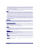
See the section titled, Definition of a "mil" for more information about reading this chart. Measurements are based on LR models set with the a 14° scan width (as opposed to the alternate Full Angle setting of 28°). Reference the Programming Manual for more information about the Half Angle feature. NOTE Specifications are subject to change without notice. Figure 9. Depth of Field (LR) Depth of Field FRONT OF SCANNER Paper Labels (LR decoded model, Code 39) 7.
See the section titled, Definition of a "mil" for more information about reading this chart. Measurements are based on XLR models set with a 10° scan angle width. NOTE Specifications are subject to change without notice. Figure 10.
LED and Beeper Indications The Base Station LED indicators and the scanner’s LEDs and beeper are used to announce system status and perform other useful signals. The tables below list the default function of each of the various indicators. Some LED and beeper indications can be disabled or modified via scanner programming. The tables indicate the default behavior of the indicators, with shaded rows representing features that are programmable. NOTE Table 1.
Table 2. Scanner YELLOW LED Functions LED INDICATION Laser on indication DURATION On Steady COMMENT The yellow LED illuminates whenever the laser is on. Table 3. Scanner BEEPER Functions SPEAKER INDICATION Scanner Not Currently Linked DURATION Six beeps consisting of 20 ms on, 20 ms off COMMENT Indicates a bar code was read before the scanner was linked to a Base Station.
SPEAKER INDICATION Transmission Error Beep DURATION High, then low, then high, then low. Indicates unsuccessful transmission to the host. Low, then medium, then high. Indicates a scanner has been successfully linked to a base station. High, then medium, then low. Indicates a scanner has been successfully unlinked from a base station. Varies. Consists of a long tone followed by multiple short tones. Enables service technicians to identify Field Replaceable Unit (FRU) errors.
LED INDICATION DURATION Continuous flashing Charge (Battery) Power COMMENT When a scanner is nested in the station, this indicates its battery is being quick charged. Lit Constantly When a scanner is nested in the station, this indicates its battery is at or near full charge. Not Lit A scanner is not present or incorrectly inserted into the station. It can also mean the battery is below 0°C (too cold for charge) Lit Constantly Indicates that power is on. a.
Enhanced Scanning for Hard-to-Read Bar Codes Decoded scanners can be programmed to decode extremely poor quality bar codes by activating advanced Quadralogic II™ Decoding. To select this feature, see the Programming Guide. Scanner programming can also be performed using your PC and the Configurator Express™ On-Screen Programming Kit. Information about manuals, kits and programming software for this product are available at our website. See the back cover for our web address. NOTE Figure 11.
NOTE Figure 11 above shows label placement ONLY. For actual regulatory, patent and other applicable information, view the labels on the product itself, or call your nearest sales or service representative. Laser Cautions The PowerScan RF bar code scanner is certified in the U.S. to conform to the requirements of DHHS/CDRH 21CFR Subchapter J for Class II laser products (SR and LR) and Class IIIa (XLR). Class II and IIIa products are not considered to be hazardous.
Radio Frequency Interference This device complies with Part 15 of the FCC Rules. Operation is subject to the following two conditions: 1. This device may not cause harmful interference, and 2. This device must accept any interference received, including interference that may cause undesired operation. This Class A digital apparatus complies with Canadian ICES-003. Cet appareil numérique de la classe A est conforme à la norme NMB003 du Canada.
Maintenance The scan window will require occasional cleaning to remove smudges, dust and other debris. To ensure optimal performance, clean the Scan Window using a soft cloth or lens tissue dampened with isopropyl alcohol (or equivalent). See Figure 12. The scanner body can also be cleaned using this method. Figure 12.
Troubleshooting Troubleshoot your RF scanning system by performing the following checks: For the RF system, ensure that... • the battery is charged. See “Battery Charging and Maintenance” on page 10. • the battery is properly installed. See “Installing the Battery” on page 4. • the scanner is linked to the desired Base Station. See “Linking the Scanner to a Base Station” on page 7.
Sample Bar Codes Use these test bar codes to check the scanner’s ability to read the various symbologies represented. Code 128 C o d e 1 2 8 . T e s t Code 39 C O D E 3 9 . T E S T Interleaved 2 of 5 0 1 2 3 4 5 6 7 8 9 Standard 2 of 5 1 2 3 4 5 6 7 8 9 0 Codabar A $ 9 9 . 9 5 A Code 93 Co d e User’s Guide 9 3 .
MSI/Plessey 4 14476925 UPC-A 00112 23344 0 0 4 9 UPC-A with 2 digit Add-on 0 60992 01118 7 6 9 0 0 0 UPC-A with 5 digit Add-on 0 08029 51041 8 UPC-E 0 998875 0 EAN-8 0021 0126 EAN-13 1 101234 567891 28 PowerScan® RF Scanner
DEUTSCHES INHALTSVERZEICHNIS Auspacken und Überprüfen Ihres Scanners ................................................................31 Referenzen ..................................................................................................................31 Anweisungen für den Schnellstart ...............................................................................31 Einlegen der Batterie ............................................................................................
Datalogic Scanning Inc. 959 Terry Street Eugene, Oregon 97402 Tel.: (541) 683-5700 Fax: (541) 345-7140 Datalogic, das Datalogic-Logo, Quadralogic II und PowerScan sind eingetragene Warenzeichen der Datalogic Scanning, Inc. Alle anderen hier genannten Waren-zeichen und Handelsnamen sind Eigentum der jeweiligen Besitzer. Alle Rechte vorbehalten. Ohne die vorherige schriftliche Zustimmung der Datalogic Scanning, Inc.
Auspacken und Überprüfen Ihres Scanners Nachdem Sie Ihren neuen Scanner ausgepackt haben, überprüfen Sie den Inhalt des Lieferkartons, ob auch alle von Ihnen bestellten Teile geliefert wurden: • • • • PowerScan® RF Handscanner Batterie/n Benutzerhandbuch (dieses Handbuch) zusätzliches Zubehör, das Sie bestellt haben. (Der Scanner kann mit oder ohne Zubehör-Kit bestellt werden) Wenn Ihr Paket falsche Teile enthält oder wenn Teile fehlen, wenden Sie sich bitte an Ihre Verkaufsstelle.
Einlegen der Batterie Hinweis Für eine maximale Lebensdauer sollten die Batterien vor der ersten Anwendung immer vollständig aufgeladen sein. (Siehe “Batterieaufladung und Wartung” auf Seite 38). Richten Sie die Batterie wie in Abbildung 1 gezeigt aus und drücken Sie die Batterie dann so weit in den Scanner, bis sie einrastet. Die Batterie wird herausgenommen, indem Sie auf die Lösetasten an beiden Seiten des Batterieteils drücken und die Batterie gerade aus dem Scanner herausziehen.
Überprüfen des Sobald die aufgeladene Batterie in den Scanner eingelegt wurde, scanScannerbetriebes nen Sie jene Muster-Barcodes auf den letzten Seiten dieses Handbuches, die der Symbolik entsprechen, für die Ihr Scanner programmiert ist. Wenn Sie sich über die Vorgehensweise unsicher sind, lesen Sie den Abschnitt dieses Handbuches "Wie wird gescannt".
Abbildung 2 Anschließen/Trennen des Schnittstellen-(I/F)Kabels a b c 2. Lesen Sie im Hauptterminal-Handbuch die erforderlichen Kommunikationsparameter für das Hauptterminal nach (z.B. Baud-Rate, Parität, usw.) und ändern Sie falls erforderlich die programmierten Parameter, damit diese mit den Anforderungen übereinstimmen.
4. Schließen Sie das Stromkabel des AC-Adapters an die Basisstation an und stecken Sie den AC/DC-Adapter in die Wandsteckdose (siehe Abbildung 3). Die Strom-LED der Basisstation leuchtet, wenn die Einheit korrekt an das Stromnetz angeschlossen ist. Abbildung 3: Die Basisstation mit dem Stromnetz verbinden 5. Schalten Sie den Strom für das Hauptterminal an. 6.
Die bestehende Systemkonfiguration der Basisstation kann automatisch auf den Scanner übertragen werden. Dieses Merkmal der automatischen Übertragung kann konfiguriert und abgestellt werden. Für weitere Informationen zu diesem Merkmal siehe Systemhandbuch. Bei einer Übertragung tritt eine leichte Verzögerung der Anzeige der Verbindungsüberprüfung auf.
Prüfen der Verbindung Scanner-anBasisstation Halten Sie den verbundenen Scanner auf einen Muster-Barcode der letzten Seiten dieses Handbuches und ziehen Sie den Auslöser (für Tipps zum Scannen von Barcodes siehe "Wie wird gescannt"). Während Sie den Barcode scannen, beobachten Sie die LED-Anzeige TX/RX (übertragen/empfangen) auf der Basisstation und/oder die grüne LED am Scanner. Die LEDs sollten vorübergehend aufblinken, wenn die beiden Geräte miteinander in Verbindung sind.
Anwenden des PowerScan RF-Systems Dieser Abschnitt behandelt die folgenden Punkte: • Batterieaufladung und Wartung • Wie wird gescannt • LED- und Signal-Anzeigen Batterieaufladung und Wartung Hinweis Wenn der Scanner in Betrieb ist, wird über ein wiederholtes zweimaliges Blinksignal der grünen LED des Scanners jedes Mal ein niedriger Batteriezustand angezeigt, wenn der Auslöser vor der Aktivierung des Lasers gezogen wird. Diese Anzeige kann über die Kundenprogrammierung abgestellt worden sein.
Ein schnelles Blinken zeigt an, dass das Aufladen stattfindet. Ein schnelles Aufladen erfolgt, wenn die Batterietemperatur zwischen 10°C (50°F) und 46°C (115°F) liegt, und/oder die Batteriespannung zwischen 2,0 und 3,2 V liegt. Die Ladezeit beträgt weniger als 4,2 Stunden. Die schnelle Aufladung wird bei einer 90 bis 95%-igen Batterieleistung abgeschlossen. Die Aufladungs-LED leuchtet kontinuierlich, wenn die Batterie langsam aufgeladen wird oder wenn der Ladezyklus abgeschlossen ist.
Vier-Stationen- Wenn Sie über ein Vier-Stationen-Ladegerät verfügen, dann werden Ladegerät die Batterien zur Aufladung wie in Abbildung 5 gezeigt eingelegt. Eine 90%-ige Aufladung wird in nur zwei Stunden erzielt, wenn dieses zusätzliche Zubehör verwendet wird - dass entspricht der Hälfte der Zeit, die für eine Aufladung über die Basisstation erforderlich ist.
Wie wird gescannt Abbildung 6 zeigt einige Tipps, wie Sie die besten Ergebnisse beim Scannen erzielen können: 1. Der Scanner muss mit einem kleinen Winkel zum Barcode gehalten werden. 2. Der Laserstrahl muss den gesamten Barcode überqueren. Der Scanner kann nicht korrekt einlesen, wenn nicht der gesamte Barcode gescannt wird.
Feldtiefe Derzeit gibt es für den Scanner vier verschiedene Reichweitenmodelle. Abhängig vom Modelltyp Ihres Scanners, müssen Sie die Einheit mit einem bestimmten Abstand vom Barcode halten, um ein optimales Ergebnis beim Scannen zu erzielen. Die folgenden Diagramme geben die Feldtiefen für jedes der Modelle an, wenn Barcodes von Grad A, Code 39 gescannt werden: Standardreichweite (SR), hohe Dichte (HD), große Reichweite (LR) und extra große Reichweite (XLR). Ein "Mil" ist gleich 0,001 Inch.
Für weitere Informationen zu diesen Diagrammen siehe Abschnitt "Definition eines "Mil"". Die Messungen basieren auf den Einstellungen der HDModelle mit der standardmäßigen 28° Scanbreite (im Gegensatz zu der Halbwinkeleinstellung von 14°). Für weitere Informationen über Halbwinkelmerkmale siehe "Programmierhandbuch". Hinweis Diese Spezifikationen können Änderungen ohne vorige Mitteilung unterliegen.
Für weitere Informationen zu diesen Diagrammen siehe Abschnitt "Definition eines "Mil"". Die Messungen basieren auf den Einstellungen der LRModelle mit der standardmäßigen 14° Scanbreite (im Gegensatz zu der alternativen Vollwinkeleinstellung von 28°). Für weitere Informationen über Halbwinkelmerkmale siehe "Programmierhandbuch". Hinweis Diese Spezifikationen können Änderungen ohne vorige Mitteilung unterliegen.
Für weitere Informationen zu diesen Diagrammen siehe Abschnitt "Definition eines "Mil"". Die Messungen basieren auf den Einstellungen der XLRModelle mit der 10° Scanwinkelbreite. Diese Spezifikationen können Änderungen ohne vorige Mitteilung unterliegen.
LED- und Signal-Anzeigen Die LED-Anzeigen der Basisstation und die LEDs des Scanners sowie die Pieptöne geben den Systemstatus an und führen weitere nützliche Signale durch. Die folgende Tabelle listet die Standardvorgaben für jede der verschiedenen Anzeigen auf. Hinweis Einige LEDs und Signal-Anzeigen können abgestellt oder über die Scanner-Programmierung geändert werden.
Tabelle 2: Gelbe LED-Funktionen des Scanners LEDAnzeige Dauer Anzeige Laser an Kommentar Die gelbe LED leuchtet immer dann, wenn der Laser eingeschaltet ist.
Anzeige Lautsprecher Dauer Zeigt an, dass eine erfolgreiche Barcode-Übertragung zum Hauptterminal (konfigurierbar), ein erfolgreicher Kanalwechsel oder eine erfolgreiche Übertragung einer neuen Konfiguration zum Hauptterminal stattgefunden hat.
LEDAnzeige Dauer leuchtet über eine variable Zeitdauera TX/RX (Übertragen/ Empfangen) fortlaufendes schnelles Blinken bei angelegter Netzspannung Verschieden. Besteht aus einem langen Blinken gefolgt von vielen kurzen Blinken fortlaufendes Blinken Kommentar Zeigt eine bestehende Kommunikation zur oder von der Basisstation an. Zeigt ein beschädigtes Empfangsgerät an. Ermöglicht es dem Servicetechniker, einen Fehler der Feld-austauschbaren Einheit (FRU) zu identifizieren.
Aktive Die aktiven (aktivierten) Barcodesymboliken der werksseitigen StanSymboliken dardvorgaben sind: • Code 39 (C39) • Code 128 (C128) • Überlappung 2 von 5 (I 2 von 5) Ihr Scanner sollte mit diesen werksseitigen Einstellungen der Standardvorgaben vorprogrammiert sein, sofern ... ... Ihnen der Scanner nicht mit einer besonderen Kundenkonfigurations-Einstellung geliefert wurde. ... Sie oder ein anderer Anwender keine Änderungen an der Scannerprogrammierung vorgenommen haben.
Abbildung 11: Scanner-Etikettierung und Nomenklatur 2 MODEL: CLASS No. SERIAL No. MFG. DATE: FREQ: 1 RF Complies with 21CFR 1040 and part 15 of FCC Rules. Applicable patents are listed on label inside unit. C ACN 073200496 XXXXX LASER RADIATION-DO NOT STARE INTO BEAM 1mw - 650-685nm CLASS 2 LASER PRODUCT Based on 100 sec.
Warnhinweise für Laseranwendung Der PowerScan RF Barcodescanner ist in den USA zertifiziert und entspricht den Anforderungen von DHHS/CDRH 21 CFR Unterkapitel J für Laserprodukte der Klasse II (SR und LR) und Klasse IIIa (XLR). Produkte der Klasse II und IIIa sind nicht als gefährlich eingestuft.
Hochfrequente Störungen Dieses Gerät erfüllt Teil 15 der FCC-Bestimmungen. Der Betrieb unterliegt den folgenden zwei Bedingungen: 1. Dieses Gerät verursacht keine schädlichen Störungen. 2. Dieses Gerät akzeptiert alle empfangenen Störungen, einschließlich Störungen, die einen nicht gewünschten Betrieb verursachen. Dieser digitale Apparat der Klasse A erfüllt Canadian ICES-003. Cet appareil numérique de la classe A est conforme à la norme NMB003 du Canada.
Wartung Das Scanfenster muss gelegentlich gereinigt werden, um Schmutz, Staub und andere Rückstände zu beseitigen. Für eine optimale Leistung reinigen Sie das Scanfenster mit einem weichen Tuch oder einem Linsentuch, das mit Isopropylalkohol (oder Ähnliches) angefeuchtet ist. Siehe Abbildung 12. Der Scannerkörper kann ebenso mit dieser Methode gereinigt werden.
Fehlersuche Sie führen die Fehlersuche für Ihr RF-Scanningsystem nach den folgenden Checks durch: Für das RF-System vergewissern Sie sich, dass • die Batterie geladen ist. Siehe “Batterieaufladung und Wartung” auf Seite 38. • die Batterie korrekt eingelegt ist. Siehe “Einlegen der Batterie” auf Seite 32. • der Scanner mit der gewünschten Basisstation verbunden ist. Siehe “Verbinden des Scanners mit der Basisstation” auf Seite 35.
dass das Problem bei den Barcodes liegt, prüfen Sie, ob der Scanner einen Muster-Barcode von den folgenden Seiten lesen kann. • die programmierbare Einstellung für fortgeschrittene Quadralogic II™-Dekodierung optimal für Ihr System eingestellt ist. (Siehe “Erweitertes Scannen für schlecht lesbare Barcodes” auf Seite 50.
Muster-Barcodes Verwenden Sie diese Test-Barcodes, um die Fähigkeit des Scanners zum Einlesen der verschiedenen Symboliken zu prüfen. Code 128 C o d e 1 2 8 . T e s t Code 39 C O D E 3 9 . T E S T Überlappend 2 von 5 0 1 2 3 4 5 6 7 8 9 Standard 2 von 5 1 2 3 4 5 6 7 8 9 0 Codabar A $ 9 9 . 9 5 A Code 93 C o Benutzerhandbuch d e 9 3 .
MSI/Plessey 4 14476925 UPC-A 00112 23344 0 0 4 9 UPC-A mit 2 Zeichen Add-on 0 60992 01118 7 6 9 0 0 0 UPC-A mit 5 Zeichen Add-on 0 08029 51041 8 UPC-E 0 998875 0 EAN-8 0021 0126 EAN-13 1 101234 567891 58 PowerScan® RF Handstrichcodeleser
FRANÇAIS SOMMAIRE Déballage et inspection de votre scanner ...................................................................61 References ..................................................................................................................61 Instructions Pour le Demarrage Rapide ......................................................................61 Installation de la Batterie .......................................................................................62 Vérification du scanner ..
Datalogic Scanning Sarl LES ULIS Cedex, France Ph: [33].01.64.86.71.00 Fax: [33].01.64 46.72.44 Datalogic, le logo Datalogic, Quadralogic et Powerscan sont des marques déposées de Datalogic Scanning, Inc. . Toute autre marque ou nom déposé mentionnés ci-après sont les biens de leur propriété respective. Tous les droits sont réservés.
Déballage et inspection de votre scanner Après avoir ôté de son emballage votre lecteur, bien vérifier le contenu du carton pour s'assurer qu'aucun article commandé ne manque, à savoir : • • • • Le scanner PowerScan RF ; Le(s) pack(s) batteries ; Le guide de l'utilisateur (que vous avez en main) ; Les accessoires optionnels que vous avez pu commander (le scanner peut être acheté avec ou sans kits accessoires).
Installation de la Batterie NOTE Pour assurer un maximum d'utilisations, les batteries doivent toujours être chargées au maximum avant la première utilisation. (Voir “Chargement et maintenance de la batterie” en page 67.) Orientez la batterie selon la Schéma 1, puis poussez la dans le scanner jusqu'à ce que vous entendiez un clic de mise en place. Pour enlever la batterie, pressez les deux cotés de la base de la batterie et tirer la pour l'extraire du scanner. Schéma 1. Installation de la batterie 1 1.
Vérification du Une fois que la batterie chargée a été installée dans le scanner, scannez scanner les exemplaires de codes à barres à la fin de ce manuel qui correspondent aux symbologies pour lesquelles votre scanner est programmé. Si vous n'êtes pas sûre de savoir comment le faire, voyez la section " Comment Scanner " de ce manuel.
Schéma 2. Conection et Deconnection du Câble (I/F) a b c 2. Consultez votre manuel de terminal HOTE afin de déterminer les paramètres de communication requis pour le Terminal HOTE (e.g., débit, parité, etc…) et, si nécessaire, modifier les paramètres de programmation afin d'être compatible avec ces exigences.
LED de la base devrait être allumée quand l'unité est branchée à la prise. Schéma 3. Connexion de la Base a L'alimentation 5. Branchez l'alimentation du terminal HOTE. 6. Vérifiez la communication avec le terminal HOTE en pointant un exemplaire de code à barres des dernières pages du présent manuel, et appuyer sur la gâchette. (voir " Comment Scanner " pour des astuces concernant la manière de scanner des codes).Vérifiez que la base du scanner à bien envoyé les données au Terminal HOTE.
La configuration de la base peut être automatiquement chargée sur le scanner. Le téléchargement automatique est configurable et peut être désactivé. Voir " Le Manuel du Système " pour plus d'informations à ce sujet. Si un téléchargement survient, un petit délai avec l'annonce du lien de vérification aura lieu.
Utilisation du PowerScan RF Cette section couvre les sujets suivants : • Chargement et maintenance de la batterie ; • Comment Scanner ; • Indicateurs : LED et Beeper. Chargement et maintenance de la batterie NOTE Lorsque le scanner est en marche, un état de batterie faible est indiqué par deux flashs répétés de la LED verte du scanner à chaque fois que la gâchette est actionné avant d'utiliser le laser. Cet indicateur peut avoir été mis hors d'usage via la programmation client.
Des clignotements rapides indiquent que le chargement est en cours. Un chargement rapide se réalise lorsque la température de la batterie est entre 10°c et 46°c, et/ou la tension de la batterie est entre 2.0 et 3.2 V. Le temps de charge est inférieure à 4.2 heures. La fin de la charge rapide se fait approximativement à 90 et 95 % de la capacité. La LED de charge reste stable lors de la charge lente ou lorsque le cycle de charge est achevé.
Chargeur Si vous disposez d'un chargeur 4 emplacements, les batteries sont Quatre insérées pour le chargement (voir en Schéma 5). Une charge rapide (90 Emplacements %) peut être terminée au bout de 2 heures seulement en utilisant cet accessoire optionnel, la moitié du temps requis par une base.
Comment Scanner Le Schéma 6 illustre les différentes astuces pour vous aider à avoir de meilleurs résultats de scan : 1. Appliquer un angle entre le scanner et le code. Ne pas tenir le scanner perpendiculairement au code à barres. 2. Le faisceau du scanner doit entièrement traverser le code à barres. Le scanner ne peut pas lire correctement si le code à barre n'est pas entièrement scanné. Schéma 6.
Profondeur de Il y a quatre différentes profondeurs de champs pour ce scanner. En Champs fonction du type de modèle de votre scanner, vous aurez besoin de placer le pistolet à une distance déterminée du code à barres pour obtenir des résultats optimum en terme de " scanning ".
Voir la section intitulée " Définition d'un Mil " pour plus d'information sur la lecture de ce diagramme. Les mesures sont basées sur des modèles HD avec un angle de lecture de 28 ° (contrairement au demi angle de 14 °). Se référer au manuel de programmation pour plus de détails concernant les caractéristiques du demi angle. NOTE Ces spécifications peuvent changer sans avertissement. Schéma 8.
Voir la section intitulée " Définition d'un Mil " pour plus d'informations concernant la lecture de ce diagramme. Les mesures sont basées sur des modèles LR avec un angle de lecture de 14° (contrairement à l'angle de lecture de 28°). Se référer au manuel de programmation pour plus d'information concernant le demi angle. NOTE Ces spécifications peuvent être changées sans avertissement. Schéma 9.
Voir la section intitulée " Définition d'un Mil " pour plus d'informations concernant la lecture de ce diagramme. Les mesures sont basées sur des modèles XLR avec un angle de scan de 10°. Ces spécifications peuvent être changées sans avertissement. NOTE Schéma 10.
Indicateurs : LED et Beeper La LED de la base, la LED du scanner et le Beeper sont utilisés pour annoncer l'état du système et représenter les autres signaux usuels. Les tableaux ci dessous répertorient les fonctions des divers indicateurs. NOTE Certain indicateurs beeper ou LED peuvent être supprimés ou modifiés par la programmation du scanner. Les tableaux indiquent le comportement par défaut des indicateurs, chaque cellule ombrée représente des caractéristiques programmables. Table 1.
Table 2. Les fonctions de la LED jaune du scanner INDICATEUR LED Indication laser allumé DUREE COMMENTAIRES Stable Le LED jaune est allumée lorsque le laser est allumé. Table 3.
INDICATIONS HAUT PARLEUR Beep d'erreur de transmission Beep de connexion Beep de déconnexion Indication d'éléments à remplacer (FRU) DUREE Fort, puis bas, puis fort, puis bas.. COMMENTAIRES Indique l'échec de transmission à l'HOTE Faible, puis moyen, et fort Indique que le scanner a été lié à la base avec succès Fort, puis moyen, et faible. Indique que le scanner a bien été déconnecté de la base Variable.
INDICATEUR LED DUREE COMMENTAIRES Lorsqu'un scanner est emboîté dans la base, il indique que la batterie est en charge rapide Flash continus Illuminée et constamment Lorsqu'un scanner est emboîté dans la base, il indique que sa batterie est quasiment chargée. Non illuminée Un scanner n'est pas présent ou incorrectement inséré dans la base. Cela peut vouloir dire que la température de la batterie est inférieure à 0°c (trop froide pour être chargée.
Les Les symbologies actives des codes ( disponibles) dans la configuration Symbologies standard sont : Actives • Code 39 (C39) • Code 128 (C128) • 2 parmi 5 entrelacé (I2of5) Votre scanner devrait être pré programmé avec ces paramètres standards, à moins que … … il vous a été envoyé programmé avec une configuration spécifique. … Vous ou un autre utilisateur ait effectué des changements, dans la programmation du scanner.
Schéma 11. Etiquetage et Nomenclature du Scanner 2 MODEL: CLASS No. SERIAL No. MFG. DATE: FREQ: 1 RF ACN 073200496 XXXXX Complies with 21CFR 1040 and part 15 of FCC Rules. Applicable patents are listed on label inside unit. C LASER RADIATION-DO NOT STARE INTO BEAM 1mw - 650-685nm CLASS 2 LASER PRODUCT Based on 100 sec.
Securite Le scanner PowerScan RF est certifié conforme aux conditions requises par la norme DHHS/CDRH 21CFR sous chapitre J pour les scanner de classe II. Les produits de classe II ne sont pas considérés comme dangereux. Le lecteur possède une diode laser d'une longueur d'onde de 650-670 nanomètres. Il a été conçu pour que l'accès à des niveaux dangereux de lumière laser ne soit pas possible pendant l'utilisation normale, l'entretien par l'utilisateur ou les fonctions de dépannage recommandées.
Interference de la Radio Frequence Cet appareil est conforme au paragraphe 15 du règlement FCC. Les opération sont soumises aux deux conditions suivantes : 1. Cet appareil ne doit pas causer d'interférences nuisibles, et 2. Il doit accepter n'importe quelle interférence reçue, y compris les interférences pouvant provoquer un dysfonctionnement. Cet appareil numérique de classe 13 est conforme aux normes Canadiennes de réglementation des équipements provoquant des interférences.
Maintenance La fenêtre de scan nécessite un nettoyage régulier pour enlever les salissures, la poussière et autre débris. Afin d'assurer une performance optimale, nettoyez le vitre du scanner en utilisant un tissus doux imprégné d'alcool isopropyl (ou un équivalent). Voir la Schéma 12. Le corps du scanner peut aussi être nettoyé en utilisant cette méthode. Schéma 12.
• Les scanner est à une distance raisonnable de sa base, sans obstruction majeure entre l'unité radio tel qu'un mur épais ou une machine lourde. (Au moment de l'écriture de ce manuel, la portée maximum en champs libre est de 45 mètres). • Il n'y a pas de signal d'interférence local avec un autre équipement en radio fréquence. Consultez le Manuel du système concernant la sélection des canaux alternatifs. • La base est bien alimentée.
Exemplaires de Codes a Barres Utilisez ces codes à barres de test afin de définir la capacité de lecture concernant les différentes symbologies représentées. Code 128 C o d e 1 2 8 . T e s t Code 39 C O D E 3 9 . T E S T 2 parmi 5 entrelacé 0 1 2 3 4 5 6 7 8 9 2 parmi 5 standard 1 2 3 4 5 6 7 8 9 0 Codabar A $ 9 9 . 9 5 A Code 93 C o Guide de L’utilisateur d e 9 3 .
MSI/Plessey 4 14476925 UPC-A 00112 23344 0 0 4 9 UPC-A avec 2 caractères Addon 0 60992 01118 7 6 9 0 0 0 UPC-A avec 5 caractères Addon 0 08029 51041 8 UPC-E 0 998875 0 EAN-8 0021 0126 EAN-13 1 101234 567891 86 PowerScan® RF Douchette Laser
ITALIANO INDICE Disimballo e ispezione del lettore ................................................................................89 Riferimenti ...................................................................................................................89 Istruzioni per l'utilizzo rapido ........................................................................................89 Installazione della batteria ....................................................................................
Datalogic Scanning, Inc. 959, Terry Street Eugene, Oregon 87402 Telefono (541) 683-5700 Telefax (541) 345-7140 Datalogic, il logo Datalogic, Quadralogic II e PowerScan sono marchi registrati di Datalogic Scanning, Inc. Tutti gli altri marchi di fabbrica e nomi commerciali cui si farà qui riferimento appartengono ai rispettivi proprietari. Tutti i diritti riservati.
Disimballo e ispezione del lettore Dopo aver disimballato il vostro nuovo lettore, controllate il contenuto dell'imballo per assicurarvi che siano presenti tutti i componenti ordinati: • • • • Lettore manuale PowerScan RF Pacco/i batteria Guida dell'operatore (questo manuale) Eventuali accessori opzionali (il lettore può essere acquistato con o senza kit accessori) Se l'imballo contiene componenti sbagliati o mancano componenti, contattate il vostro rivenditore.
Installazione della batteria NOTA Per garantire la massima autonomia, le batterie devono sempre risultare completamente cariche prima dell'utilizzo iniziale (Vedere “Caricamento e manutenzione della batteria” a pag. 95). Orientare la batteria come indicato in Figura 1, quindi spingerla dentro il lettore fino allo scatto in posizione. Per togliere la batteria, premere sulle alette ai lati della base della batteria ed estrarla dal lettore. Figura 1. Installazione della batteria 1 1.
Verifica Dopo aver inserito una batteria carica nel lettore, effettuare la lettura funzionale del dei codici a barre riportati sul retro del manuale, corrispondenti alle lettore simbologie per le quali è programmato il lettore. Se non sapete come fare, consultate la sezione "Come effettuare la lettura".
Figura 2. Collegamento/scollegamento del cavo di interfaccia (I/F) a b c 2. Consultare il manuale del terminale host per determinare i parametri di comunicazione necessari (ad esempio parità, baud rate, ecc.) e, se necessario, modificare i parametri predefiniti per adattarli a quelli richiesti. La programmazione del lettore e può essere effettuata utilizzando: - Software di programmazione Configurator Express™ - Guida di programmazione del lettore di codici a barre PowerScan® Vedere la sez.
4. Collegare il cavo di alimentazione dell'adattatore di corrente al modulo base e quindi inserire l'adattatore in una presa di corrente (Figura 3). Il LED di alimentazione del modulo base si illumina quando l'unità è alimentata correttamente. Figura 3. Collegamento di alimentazione del modulo base 5. Accendere il terminale host. 6.
La configurazione di sistema del modulo base può essere scaricata automaticamente sul lettore. Questa funzione è configurabile e può essere disabilitata. Vedere il Manuale del sistema per ulteriori informazioni su tale funzione. Lo scaricamento dei dati determina un leggero ritardo del segnale di conferma del collegamento.
Utilizzo di PowerScan RF Questa sezione descrive i seguenti argomenti: • Caricamento e manutenzione della batteria • Come effettuare la lettura • Segnalazioni acustiche e luminose (LED) Caricamento e manutenzione della batteria NOTA Quando il lettore è in uso, la condizione di batteria scarica viene indicata attraverso una segnalazione ripetuta di doppio lampeggio del LED verde del lettore ogni volta che si preme la levetta di comando prima che il laser sia attivato.
Un lampeggio rapido indica che il caricamento avviene correttamente. Il caricamento viene effettuato rapidamente quando la temperatura della batteria è compresa tra 10 °C e 46 °C e/o la carica della batteria oscilla tra 2.0 e 3.2V. Il tempo di caricamento è inferiore a 4,2 ore. Il caricamento rapido termina con la batteria approssimativamente al 90-95% della sua capacità. Il LED di carica resta acceso stabilmente con carica di mantenimento o al completamento del ciclo di carica.
Caricabatterie Se avete un caricabatterie a 4 vani, le batterie vengono inserite per il a 4 vani caricamento come indicato in Figura 5. Con questo accessorio è possibile effettuare una carica rapida del 90% in appena due ore, la metà del tempo richiesto per il caricamento sul modulo base.
Come effettuare la lettura La Figura 6 illustra alcuni suggerimenti per ottenere i migliori risultati di lettura: 1. Il lettore deve essere puntato verso il codice a barre in modo leggermente inclinato. Non tenere il lettore perpendicolare al codice a barre. 2. Il raggio laser deve attraversare l'intero codice a barre. Il lettore non può leggere correttamente se non effettua la scansione dell'intero codice a barre. Figura 6.
Profondità di Attualmente il lettore è disponibile in quattro modelli. In base al modcampo ello, il lettore deve essere tenuto ad una distanza appropriata dal codice a barre per ottenere i migliori risultati di lettura. I diagrammi riportati di seguito forniscono informazioni sulla profondità di campo di ogni modello per la lettura di codici a barre di tipo A e Code 39: standard (SR), alta densità (HD), lungo raggio (LR) e raggio extra (ELR). Un "mil" corrisponde a 0,254 millimetri.
Vedere la sezione Definizione di "mil" per ulteriori informazioni sull'interpretazione di questo grafico. Le misure si basano su modelli HD configurati con angolo di scansione standard di 28° (in contrapposizione alla configurazione ad angolo ristretto di 14°). Fare riferimento al Manuale di programmazione per ulteriori informazioni sulla configurazione ad angolo ristretto. NOTA Le specifiche possono variare senza preavviso. Figura 8.
Vedere la sezione Definizione di "mil" per ulteriori informazioni sull'interpretazione di questo grafico. Le misure si basano su modelli HD configurati con angolo di scansione standard di 28° (in contrapposizione alla configurazione ad angolo ristretto di 14°). Fare riferimento al Manuale di programmazione per ulteriori informazioni sulla configurazione ad angolo ristretto. NOTA Le specifiche possono variare senza preavviso. Figura 9.
Vedere la sezione Definizione di "mil" per ulteriori informazioni sull'interpretazione di questo grafico. Le misure si basano su modelli XLR configurati con angolo di scansione di 10°. NOTA Le specifiche possono variare senza preavviso. Figura 10.
Segnalazioni acustiche e luminose (LED) Gli indicatori LED del modulo base ed i LED e il segnalatore acustico del lettore vengono utilizzati per segnalare lo stato operativo del sistema e per fornire altre indicazioni utili. Le tabelle che seguono riportano le funzioni predefinite di ogni indicatore. Alcune segnalazioni acustiche o luminose possono essere disabilitate o modificate attraverso la programmazione del lettore.
Tabella 2. Funzioni del LED giallo del lettore Indicazione Laser attivo Durata Significato Il LED giallo si illumina ogni volta che il laser è attivo. Acceso Tabella 3. Funzioni del segnalatore acustico del lettore Segnalazione Lettore non collegato Durata 6 suoni di 20 ms ad intervalli di 20 ms Significato Indica che il codice a barre è stato letto prima che il lettore fosse collegato al modulo base.
Segnalazione Errore di trasmissione Durata Alto, basso, alto, basso Indica che la trasmissione al terminale non è andata a buon fine. Basso, medio, alto. Indica che il lettore si è connesso correttamente al modulo base. Alto, medio, basso Indica che il lettore si è disconnesso correttamente dal modulo base. Connessione Disconnessione Unità FRU Significato Variabile. Consiste in un lungo segnale seguito da segnali brevi multipli. Permette ai tecnici di identificare gli errori di unità FRU.
Indicazione Durata Lampeggio continuo Quando il lettore è inserito nel modulo base, indica che la batteria si è in fase di carica rapida. Acceso Quando il lettore è inserito nel modulo base, indica che la batteria è quasi o completamente carica. Spento Il lettore non è presente oppure è inserito male nel modulo. Inoltre, può indicare che la batteria è al di sotto di 0° C (troppo fredda per caricarsi). Acceso Indica che l'unità è alimentata. Carica (batteria) Alimentazione Significato a.
Scansione avanzata per codici a barre di difficile lettura I lettori a decodifica possono essere programmati per la lettura di codici a barre di qualità molto scadente attivando la decodifica avanzata Quadralogic II™. Per attivare questa funzione, consultare la Guida di programmazione. La programmazione del lettore può essere effettuata anche mediante il PC e il kit di programmazione Configurator Express™.
La Figura 11 illustra SOLO la posizione dell'etichetta. Per le normative vigenti, brevetti e altre informazioni pertinenti, vedere le etichette sul prodotto o consultare il rivenditore o un centro di assistenza. NOTA Avvertenze sul laser Il lettore di codici a barre PowerScan RF è certificato negli Stati Uniti per la conformità ai requisiti dello standard DHHS/CRH 21CFR Subchapter J for Class II laser products (SR and LR) and Class IIIa (XLR).
Disturbi in radiofrequenza Questo dispositivo è conforme alla sez. 15 delle norme FCC. L'utilizzo è subordinato alle due condizioni seguenti: 1. Il dispositivo non deve causare interferenze dannose, e 2. Il dispositivo deve sopportare le interferenze captate, incluse quelle che possono determinare un funzionamento anomalo. Questo dispositivo digitale di Classe A è conforme alle normative canadesi ICES-003. Cet appareil numérique de classe A est conforme à la norme NMB-003 du Canada.
Manutenzione Il vetro del lettore deve essere pulito saltuariamente per rimuovere tracce di sporcizia, polvere ed altre impurità. Per ottenere un funzionamento ottimale, pulire la finestra di scansione con un panno morbido o una salvietta per occhiali inumidita con alcool isopropilico (o equivalente). Vedere la Figura 12. Anche il corpo del lettore può essere pulito con la stessa modalità. Figura 12.
Risoluzione dei problemi Provate ad eliminare eventuali malfunzionamenti del sistema di lettura in radiofrequenza effettuando i seguenti controlli: • Per il sistema RF, verificare che: • La batteria sia carica. Vedere “Caricamento e manutenzione della batteria” a pag. 95. • La batteria sia correttamente installata. Vedere “Installazione della batteria” a pag. 90. • Il lettore sia collegato al modulo base prescelto. Vedere “Collegamento del lettore al modulo base” a pag. 93.
(Vedere “Scansione avanzata per codici a barre di difficile lettura” a pag. 107.) Codici a barre campione Utilizzare questi codici a barre di riferimento per verificare la funzionalità del lettore nella lettura delle diverse simbologie rappresentate. Code 128 C o d e 1 2 8 . T e s t Code 39 C O D E 3 9 . T E S T Interleaved 2 of 5 0 1 2 3 4 5 6 7 8 9 Standard 2 of 5 1 2 3 4 5 6 7 8 9 0 Codabar A $ 9 9 . 9 5 A Code 93 C o 112 d e 9 3 .
MSI/Plessey 4 14476925 UPC-A 00112 23344 0 0 4 9 UPC-A con 2 cifre aggiuntive 0 60992 01118 7 6 9 0 0 0 UPC-A con 5 cifre aggiuntive 0 08029 51041 8 UPC-E 0 998875 0 EAN-8 0021 0126 EAN-13 1 101234 567891 Manuale d’Istruzioni 113
NOTE 114 PowerScan® RF Lettore portatile di codici a barre
DECLARATION OF CONFORMITY Datalogic hereby declares that the Equipment specified below has been tested and found compliant to the following Directives and Standards: Directives: EMC 89/336/EEC Low Voltage 73/23/EEC R&TTE 1999/5/EC Standards: EN 300 683:1997 - Radio EN 300 220-3:2000 - Radio Immunity EN 60950:2000 - ITE Safety EN 60825-1/A2:2001 - Laser Safety Equipment Type: Product Model Name: Placed into EU Service: Serial No.
Australia Japan Datalogic Scanning Pty Ltd Datalogic Scanning KK North Ryde, Australia Shinagawa, Tokyo, Japan Telephone: [61] (2) 9870 3200 Telephone: 81 (0)3 3491 6761 Fax: [61] (2) 9878 8688 Fax: 81 (0)3 3491 6656 France and Benelux Latin America Datalogic Scanning Sarl Datalogic Scanning, Inc LES ULIS Cedex, France Miami, Florida, USA Telephone: [33].01.64.86.71.00 Telephone: (305) 591-3222 Fax: [33].01.64 46.72.