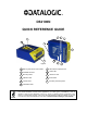
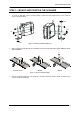
DS2100N QUICK REFERENCE GUIDE 4 2 1 5 6 3 7 11 10 9 Figure A NOTE 8 1 Warning and Device Class Labels 7 Laser Beam Output Window 2 "POWER ON" LED 8 "COM" LED 3 Mounting Holes 9 "STATUS" LED 4 "READY" LED 10 Push Button 5 "GOOD" LED 11 Accessory Mounting Holes 6 "TRIGGER" LED This manual illustrates a Stand Alone application. For other types of installations, such as ID-NET™, Pass-Through, Multiplexer Layout, etc.
DS2100N QUICK GUIDE UPDATES AND LANGUAGE AVAILABILITY UK/US The latest drivers and documentation updates for this product are available on Internet. Log on to: www.automation.datalogic.com I Su Internet sono disponibili le versioni aggiornate di driver e documentazione di questo prodotto. Questo manuale è disponibile anche nella versione italiana. Collegarsi a: www.automation.datalogic.com F Les versions mises à jour de drivers et documentation de ce produit sont disponibles sur Internet.
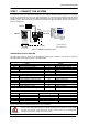
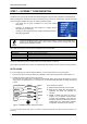
DS2100N QUICK GUIDE STEP 1 – CONNECT THE SYSTEM To connect the system in a Stand Alone configuration, you need the hardware indicated in Figure 1. In this layout the data is transmitted to the Host on the main serial interface. In Local Echo communication mode, the RS232 auxiliary interface can be used to transmit data independently from the main interface selection.
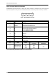
DS2100N QUICK GUIDE 25-pin Connector Pinout for DS2100N The table below gives the pinout of the 25-pin male D-sub connector for connection to the power supply and input/output signals.
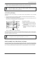
DS2100N QUICK GUIDE STEP 2 – MOUNT AND POSITION THE SCANNER 1. To mount the DS2100N, use the mounting bracket to obtain the most suitable position for the reader as shown in the figures below. Skew Pitch Tilt Skew 2. Figure 3 - Positioning with Mounting Bracket When mounting the DS2100N take into consideration these three ideal label position angles:, Skew 10° to 30°, Tilt 0° and Pitch 0°. P T S Assure at least 10° Minimize Minimize Figure 4 –, Skew, Tilt and Pitch Angles 3.
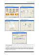
DS2100N QUICK GUIDE STEP 3 – X-PRESS™ CONFIGURATION X-PRESS™ is the intuitive Human Machine Interface designed to improve ease of installation and maintenance.
DS2100N QUICK GUIDE 3. Exit the process by pressing the X-PRESS™ push button once. The scanner will restart at the end of the process, and then the detected barcodes are automatically configured in scanner memory. NOTE If the barcode cannot be read because of low contrast or excessive ambient light, you can perform the AutoSetup function to optimize the optical parameters. Then you can perform AutoLearn to recognize the barcode symbology.
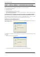
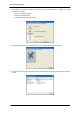
DS2100N QUICK GUIDE STEP 4 – INSTALL GENIUS™ CONFIGURATION PROGRAM Genius™ is a Datalogic scanner configuration tool providing several important advantages: • Wizard approach for new users; • Multi-language version; • Defined configuration directly stored in the reader; • Communication protocol independent from the physical interface allowing to consider the reader as a remote object to be configured and monitored.
DS2100N QUICK GUIDE a. Barcode selection and definition b. Operating mode selection and definition c. Digital Outputs configuration d. Hardware interface selection e. Output data format configuration The On Line operating Mode requires the reader to be connected to an External Trigger/Presence Sensor using I1A and I1B inputs. The Automatic operating mode does not require connection to an external Presence Sensor.
DS2100N QUICK GUIDE 2. After defining the parameter values the following window appears allowing to complete the reader configuration as follows: • Saving the configuration to disk; • Switching to Advanced mode; • Sending the configuration to the scanner. 3. After sending the configuration to the scanner you have completed the configuration process. 4. By clicking Finish, the System Information window will be displayed with specific information concerning the scanner.
DS2100N QUICK GUIDE STEP 5 – TEST MODE Use a code suitable to your application to test the system. Alternatively, you can use the Datalogic Test Chart (Interleaved 2/5 or Code 39). 1. Enter the Test mode function by holding the X-PRESS™ push button pressed until the TEST LED is on. 2. Release the button to enter the Test mode function. Once entered, the Bar-Graph on the five LEDs is activated and if the scanner starts reading barcodes the Bar-Graph shows the Good Read Rate.
DS2100N QUICK GUIDE ADVANCED SCANNER CONFIGURATION For further details on advanced product configuration, refer to the complete Reference Manual on the installation CD-ROM or downloadable from the web site through this link: www.automation.datalogic.com/ds2100n. The following are alternative or advanced scanner configuration methods: HOST MODE PROGRAMMING The scanner can also be configured from a host computer using the Host Mode programming procedure, by commands via the serial interface.
DS2100N QUICK GUIDE APPENDIX READING DIAGRAMS DS2100N-1200 (Standard Resolution) 0 0 5 4 CONDITIONS 3 Optic Version = Linear Code = Interleaved 2/5 Code 39 PCS = 0.90 Pitch angle = 0° Skew angle = 15° Tilt angle = 0° *Reading Conditions = Standard *Scan Speed = 500 scans/sec 2 * Parameter selectable in Genius™ 2 1 20 2 40 3 60 4 5 6 7 8 9 10 11 12 (in) 80 100 120 140 160 180 200 220 240 260 280 300 (mm) 120 100 80 60 40 1 20 0 0 1 20 0.20 mm (8 mils) 0.30 mm (12 mils) 0.
DS2100N QUICK GUIDE DS2100N-1204 High Performance (Standard Resolution) 0 1 0 5 Optic Version = Linear Code = Interleaved 2/5 Code 39 PCS = 0.90 Pitch angle = 0° Skew angle = 15° Tilt angle = 0° *Code Resolution: High - for 0.30 mm (12 mils) codes and smaller Standard - for 0.
DS2100N QUICK GUIDE READING PERFORMANCE Version 1XX0 1XX4 2XX0 2XX4 Reading Distance Max Code Resolution mm (mils) 0.20 (8) 0.20 (8) 0.15 (6) 0.12 (5) 40 mm (1.6 in) - 300 mm (11.8 in) on 0.50 mm (20 mils) codes 50 mm (1.8 in) - 310 mm (11.8 in) on 0.50 mm (20 mils) codes 30 mm (1.2 in) - 90 mm (3.5 in) on 0.30 mm (12 mils) codes 45 mm (1.8 in) - 100 mm (3.9 in) on 0.
DS2100N QUICK GUIDE MECHANICAL INSTALLATION 84 3.31 23.3* 0.92 4 0.16 10.3 0.41 10.3 0.41 14 0.55 14.7 0.58 M 4 n° 4 DS2100N GOOD 40 1.57 68 2.68 46 1.81 40 1.57 READY SETUP TRIGGER LEARN COM TEST STATUS X PRESS 32.7 1.29 INTERFACE mm inch * The quote refers to the scan line Figure 10 – DS2100N Overall Dimensions 9 2.5 mm Figure 11 – Mounting Bracket Overall Dimensions 16 4.2 n° 2 4. 2 2.5 17.5 30 73 40 20° 13.8 R 42 90° 1 x 45° n° 2 7.8 4.
DS2100N QUICK GUIDE PATENTS This product is covered by one or more of the following patents: U.S. patent: 5,992,740 European patent: 789,315 B1 COMPLIANCE LASER SAFETY The scanner is classified as a Class 2 laser product according to EN 60825-1 regulations and as a Class II laser product according to CDRH regulations.
DECLARATION OF CONFORMITY 07 Datalogic Automation S.r.l. Via S.