DS6300 QUICK REFERENCE GUIDE
CONTENTS DS6300-100-010 MASTER/SLAVE MODEL ...........................................................................................................1 DS6300-100-011 PROFIBUS MODEL.....................................................................................................................8 DS6300-100-012 ETHERNET MODEL ..................................................................................................................13 DS6300-100-015 DEVICENET MODEL...................................
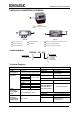
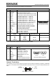
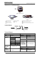
DS6300 MASTER/SLAVE MODEL DS6300-100-010 MASTER/SLAVE MODEL 1 Figure A 1 Laser Beam Output Window 1 5 1 3 4 3 2 2 Figure B Figure C 1 Programming Keypad 4 Power On LED (Red) 1 Main/Aux.
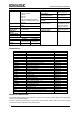
DS6300 MASTER/SLAVE MODEL SOFTWARE FEATURES Readable Codes Interleaved 2/5 Code 39 standard Codabar Code 128 EAN 128 Code 93 (Standard & Full ASCII) EAN/UPC (including Add-on 2 and Add-on 5) Code Selection Up to 10 codes during one reading phase Headers and Up to 128-byte headers and128Terminators byte terminators Operating On Line, Automatic, Test Modes Config. Mode Genius™ utility program Param. Storage Non-volatile internal FLASH PHYSICAL FEATURES Dimensions mm (inch) Weight Std Models 110x113x99 (4.
DS6300 MASTER/SLAVE MODEL The details of the connector pins are indicated in the following table: 25-pin D-Sub Connector Pinout Pin Name Function Chassis - internally connected to GND Cable shield connected to chassis 20 RXAUX Receive data of auxiliary RS232 (referred to GND) 21 TXAUX Transmit data of auxiliary RS232 (referred to GND) 8 OUT 1+ Configurable digital output 1 – positive pin 22 OUT 1Configurable digital output 1 – negative pin 11 OUT 2+ Configurable digital output 2 – positive pin 12 OUT 2Co
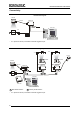
DS6300 MASTER/SLAVE MODEL Connectivity: Point-to-Point Layout DS6300 CAB-600X C-BOX 100 Local Host *P.S. PG6000 * P.S. (Presence Sensor) connected to External Trigger/PS input. Pass Through Layout *P.S. *P.S. Gryphon DS4600A < T < < EN CAB-600X C-BOX 100 C-BOX 100 C-BOX 100 AUX MAIN *P.S. 1 2 2 Local Host 1 PWR-120 1 Main Serial Interface * 4 DS4600A EN T < DS6300 2 Auxiliary Serial Interface P.S. (Presence Sensor) connected to External Trigger/PS input.
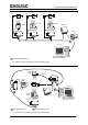
DS6300 MASTER/SLAVE MODEL Multiplexer Layout *P.S. *P.S. *P.S. DS4600A < DS4600A < DS6300 EN T EN T < < PWR-120 CAB-600X C-BOX 100 C-BOX 100 C-BOX 100 #31 MX4000 1 #0 #1 Local Host 1 RS485 HD Main Interface * P.S. (Presence Sensor) connected to External Trigger/PS input. RS232 Master/Slave Layout DS6300 Master CAB-600X C-BOX 100 2 < < EN T DS4600A Slave 1 1 *P.S.
DS6300 MASTER/SLAVE MODEL Local Lonworks Network CAB-60XX CAB-610X BTK-6000 C-BOX 100** Master Encoder*** BTK-6000 Slave 1 *P.S. Local Host CAB-63XX PWR-120 Small Synchronized Network with 2 Readers * P.S. (Presence Sensor) connected to External Trigger/PS input. ** C-BOX 100 modified to accept scanner power. *** Encoder connected to IN2/ENC input. Local Lonworks Network Slave 2 Master Slave 1 CAB-610X CAB-610X BTK-6000 C-BOX 100** CAB-600X *P.S.
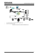
DS6300 MASTER/SLAVE MODEL Large Synchronized Network ** * * P.S. (Presence Sensor) connected to External Trigger/PS input. ** Encoder connected to ENC input.
DS6300 PROFIBUS MODEL DS6300-100-011 PROFIBUS MODEL 1 Figure A 1 Laser Beam Output Window 3 5 1 3 4 1 2 2 Figure B Figure C 1 Programming Keypad 4 Power On LED (Red) 1 Profibus 9-pin Female Connector (white) 2 TX Data LED (Green) 5 LCD Display 2 Lonworks 9-pin Female Connector 3 Phase On LED (Yellow) 3 Main/Aux.
DS6300 PROFIBUS MODEL SOFTWARE FEATURES Readable Codes Interleaved 2/5 Code 39 standard Codabar Code 128 EAN 128 Code 93 (Standard & Full ASCII) EAN/UPC (including Add-on 2 and Add-on 5) Code Selection Up to 10 codes during one reading phase Headers and Up to 128-byte headers and128Terminators byte terminators Operating On Line, Automatic, Test Modes Config. Mode Genius™ utility program Param. Storage Non-volatile internal FLASH PHYSICAL FEATURES Dimensions mm (inch) Weight Std Models 110x113x99 (4.33x4.
DS6300 PROFIBUS MODEL 26-pin D-Sub Connector Pinout Pin Name Function Chassis - internally connected to GND Cable shield connected to chassis 20 RXAUX Receive data of auxiliary RS232 (referred to GND) 21 TXAUX Transmit data of auxiliary RS232 (referred to GND) 8 OUT 1+ Configurable digital output 1 – positive pin 22 OUT 1Configurable digital output 1 – negative pin 11 OUT 2+ Configurable digital output 2 – positive pin 12 OUT 2Configurable digital output 2 – negative pin 9 1 16 OUT 3A Configurable digita
DS6300 PROFIBUS MODEL Connectivity: Point-to-Point Layout Remote Host Fieldbus Network DS6300 C-BOX 100 CAB-601X *P.S PG6000 * P.S. (Presence Sensor) connected to External Trigger/PS input. Pass Through Layout Remote Host *P.S. *P.S. Gryphon DS4600A < < EN T CAB-601X C-BOX 100 AUX DS4600A EN T < DS6300 < Fieldbus Network C-BOX 100 C-BOX 100 *P.S. 2 1 2 1 PWR-120 1 Main Serial Interface * 2 Auxiliary Serial Interface P.S.
DS6300 PROFIBUS MODEL Local Lonworks Network Remote Host Fieldbus Network Slave 2*** Slave 1*** Master C-BOX 100** CAB-610X CAB-610X CAB-60XX P.S.* CAB-610X Encoder**** CAB-610X CAB-610X CAB-63XX BTK-6000 Slave 5*** Slave 3*** Slave 4*** PWR-240 CAB-63XX Fieldbus Small Synchronized Network * P.S. (Presence Sensor) connected to External Trigger/PS input. ** C-BOX 100 modified to accept scanner power.
DS6300 ETHERNET MODEL DS6300-100-012 ETHERNET MODEL 1 Figure A 1 Laser Beam Output Window 3 5 1 3 4 1 2 2 Figure B Figure C 1 Programming Keypad 4 Power On LED (Red) 1 RJ45 Modular Connector for Ethernet Interface 2 TX Data LED (Green) 5 LCD Display 2 Lonworks 9-pin Female Connector 3 Phase On LED (Yellow) 3 Main/Aux.
DS6300 ETHERNET MODEL SOFTWARE FEATURES Readable Codes Interleaved 2/5 Code 39 standard Codabar Code 128 EAN 128 Code 93 (Standard & Full ASCII) EAN/UPC (including Add-on 2 and Add-on 5) Code Selection Up to 10 codes during one reading phase Headers and Up to 128-byte headers and128Terminators byte terminators Operating On Line, Automatic, Test Modes Config. Mode Genius™ utility program Param. Storage Non-volatile internal FLASH PHYSICAL FEATURES Dimensions mm (inch) Weight Std Models 110x113x99 (4.33x4.
DS6300 ETHERNET MODEL 26-pin D-Sub Connector Pinout Pin Name Function Chassis - internally connected to GND Cable shield connected to chassis 20 RXAUX Receive data of auxiliary RS232 (referred to GND) 21 TXAUX Transmit data of auxiliary RS232 (referred to GND) 8 OUT 1+ Configurable digital output 1 – positive pin 22 OUT 1Configurable digital output 1 – negative pin 11 OUT 2+ Configurable digital output 2 – positive pin 12 OUT 2Configurable digital output 2 – negative pin 9 1 16 OUT 3A Configurable digita
DS6300 ETHERNET MODEL Connectivity: Point-to-Point Layout Remote Host Fieldbus Network DS6300 C-BOX 100 CAB-601X *P.S PG6000 * P.S. (Presence Sensor) connected to External Trigger/PS input. Pass Through Layout Remote Host *P.S. *P.S. Gryphon DS4600A < < EN T CAB-601X C-BOX 100 AUX C-BOX 100 C-BOX 100 *P.S. 2 1 PWR-120 1 Main Serial Interface * 16 2 Auxiliary Serial Interface P.S. (Presence Sensor) connected to External Trigger/PS input.
DS6300 ETHERNET MODEL Local Lonworks Network Remote Host Fieldbus Network Slave 2*** Slave 1*** Master C-BOX 100** CAB-610X CAB-610X CAB-60XX P.S.* CAB-610X Encoder**** CAB-610X CAB-610X CAB-63XX BTK-6000 Slave 5*** Slave 3*** Slave 4*** PWR-240 CAB-63XX Fieldbus Small Synchronized Network * P.S. (Presence Sensor) connected to External Trigger/PS input. ** C-BOX 100 modified to accept scanner power.
DS6300 DEVICENET MODEL DS6300-100-015 DEVICENET MODEL 1 Figure A 1 Laser Beam Output Window 1 5 1 3 4 3 2 2 Figure B Figure C 1 Programming Keypad 4 Power On LED (Red) 2 TX Data LED (Green) 5 LCD Display 1 Main/Aux.
DS6300 DEVICENET MODEL SOFTWARE FEATURES Readable Codes Interleaved 2/5 Code 39 standard Codabar Code 128 EAN 128 Code 93 (Standard & Full ASCII) EAN/UPC (including Add-on 2 and Add-on 5) Code Selection Up to 10 codes during one reading phase Headers and Up to 128-byte headers and128Terminators byte terminators Operating On Line, Automatic, Test Modes Config. Mode Genius™ utility program Param. Storage Non-volatile internal FLASH PHYSICAL FEATURES Dimensions mm (inch) Weight Std Models 110x113x99 (4.33x4.
DS6300 DEVICENET MODEL The details of the connector pins are indicated in the following table: 26-pin D-Sub Connector Pinout Pin Name Function Chassis - internally connected to GND Cable shield connected to chassis 20 RXAUX Receive data of auxiliary RS232 (referred to GND) 21 TXAUX Transmit data of auxiliary RS232 (referred to GND) 8 OUT 1+ Configurable digital output 1 – positive pin 22 OUT 1Configurable digital output 1 – negative pin 11 OUT 2+ Configurable digital output 2 – positive pin 12 OUT 2Confi
DS6300 DEVICENET MODEL Connectivity: Point-to-Point Layout Remote Host Fieldbus Network DS6300 C-BOX 100 CAB-601X *P.S PG6000 * P.S. (Presence Sensor) connected to External Trigger/PS input. Pass Through Layout Remote Host *P.S. *P.S. Gryphon DS4600A < < EN T CAB-601X C-BOX 100 AUX DS4600A EN T < DS6300 < Fieldbus Network C-BOX 100 C-BOX 100 *P.S. 2 1 2 1 PWR-120 1 Main Serial Interface * 2 Auxiliary Serial Interface P.S.
DS6300 DEVICENET MODEL Local Lonworks Network Remote Host Fieldbus Network Slave 2*** Slave 1*** Master C-BOX 100** CAB-610X CAB-610X CAB-60XX P.S.* CAB-610X Encoder**** CAB-610X CAB-610X CAB-63XX BTK-6000 Slave 5*** Slave 3*** Slave 4*** PWR-240 CAB-63XX Fieldbus Small Synchronized Network * P.S. (Presence Sensor) connected to External Trigger/PS input. ** C-BOX 100 modified to accept scanner power.
DS6300 OSCILLATING MIRROR MODEL DS6300-105-0XX OSCILLATING MIRROR MODEL 1 Figure A 1 Laser Beam Output Window Oscillating mirror models are used when coverage of a large reading area is required, mainly in picket fence applications. The DS6300 scanner mounts a dedicated optic head with integrated oscillating mirror driven by a linear motor. The speed, precision, repeatability, and reliability of this driving technology assure high level performance.
DS6300 OSCILLATING MIRROR MODEL The mirror can be deflected up to 40°. Oscillation with respect to the output window median axis is asymmetrical (see figure below). ° 37.5 40° -2.5° 0° Oscillating Mirror Maximum Aperture and Asymmetry By configuring the oscillating speed up to the maximum value of 19 Hz, raster emulation can be performed for reading fast moving objects. Hz Max.
COMMON FEATURES COMMON FEATURES C-BOX 100 Pinout for DS6300: The table below gives the pinout of the C-BOX 100 terminal block connectors.
COMMON FEATURES Mechanical Installation: TM The DS6300 reader can be positioned and installed in the best way possible as a result of the Step-A-Head feature. Thanks to the separation between Head and Base, you can modify the orientation of the decoder base, and therefore display-keypad and connector panels, while keeping the optic head in the correct reading position.
COMMON FEATURES Typical Installations: Standard Installation The DS6300 scanner is mounted on the ST-237 106° mounting bracket which guarantees a built-in Skew angle (S in the figure below) of 16° with respect to the frame plane (typically the Skew angle should be between 10° - 20°). This avoids the direct reflection of the laser light emitted by the scanner.
COMMON FEATURES Focus Adjustment: The DS6300 provides a manual adjustment of the optics to optimize the reading performance by choosing the best focus between two extreme positions. The focus adjustment is continuous and not by step; thus, allowing an optimum adjustment around the selected position. The relative focus positions range from 0 to 100. The adjustment can be simply made through an external screw placed on the back of the optic HEAD and protected by a cap.
COMMON FEATURES 7) Use the ▲ (up arrow) and ▼ (down arrow) key to select the “Exit” item, then press the ENT (enter) key to confirm. The scanner exits the Main Menu and returns to its current operating mode. Focus Adjustment Screw The reader display shows the focus position only when the laser beam is activated. NOTE It is possible to visualize the focus position and the reading percentage on the terminal tool provided by the Genius™ configuration program (see Genius™ Help On-Line for details).
COMMON FEATURES Conveyor Speed (m/s) Code 128 – Ean 128 Code Resolution (mm) 0.25 0.30 0.33 0.38 0.50 0.72 1.00 0.5 8 8 9 10 12 16 22 1 9 10 11 11 13 17 23 Minimum Code Height for ACR Reading (mm) 45° 30° 1.5 2 2.5 3 0.5 1 1.5 2 11 13 15 17 5 7 8 10 12 14 16 18 6 7 9 10 13 14 16 18 6 8 9 11 13 15 17 19 7 8 10 11 15 17 19 21 8 9 11 12 19 21 22 24 10 11 13 14 24 25 27 29 13 14 15 17 2.5 11 12 12 13 14 16 18 3 13 13 14 14 15 17 20 2.5 11 12 12 13 14 16 18 3 13 13 14 14 15 17 20 2.
COMMON FEATURES Reading Diagrams: In the following reading diagrams (0,0) is the center of the laser beam output window. DS6300-100-0XX – Resolution: 0.20 mm/8 mils 10 CONDITIONS Code = Interleaved 2/5 or Code 39 PCS = 0.
COMMON FEATURES Reading Diagrams: DS6300-100-0XX – Resolution: 0.38 mm/15 mils 0 0 16 40 12 14 30 16 18 35 40 45 20 50 22 55 24 60 26 28 65 70 30 75 32 80 34 85 36 38 90 40 42 44 (in) 95 100 105 110 (cm) 14 35 12 30 10 25 Focus Position = 0 8 20 6 15 CONDITIONS Code = Interleaved 2/5 or Code 39 PCS = 0.
COMMON FEATURES Reading Diagrams: DS6300-105-0XX (Oscillating Mirror) – Resolution: 0.20 mm/8 mils 0 0 10 25 8 20 6 15 4 CONDITIONS Code = Interleaved 2/5 or Code 39 PCS = 0.90 Pitch angle = 0° Skew angle = 10° - 20° Tilt angle = 0° 6 15 8 20 10 12 14 25 30 18 16 35 40 45 20 22 55 50 Focus Position = 0 24 (in) 60 (cm) Focus Position = 40 10 2 5 0 0 -2 -5 -4 -10 -6 -15 -8 -20 -10 -25 (in) (cm) DS6300-105-0XX (Oscillating Mirror) – Resolution: 0.
COMMON FEATURES Reading Diagrams: DS6300-105-0XX (Oscillating Mirror) – Resolution: 0.38 mm/15 mils 0 0 16 40 10 12 25 30 14 16 35 18 40 45 20 50 22 55 24 60 26 28 30 65 70 75 32 34 36 80 85 90 38 40 42 (in) 95 100 105 (cm) 14 35 12 30 10 25 Focus Position = 0 8 20 6 15 CONDITIONS Code = Interleaved 2/5 or Code 39 PCS = 0.
COMMON FEATURES User Interface: RS232 PC-side connections 1 5 1 6 13 14 9 9-pin male connector Pin 2 3 5 7 8 25 25-pin male connector Name RX TX GND RTS CTS Pin 3 2 7 4 5 Name RX TX GND RTS CTS How To Build A Simple Interface Test Cable: The following wiring diagram shows a simple test cable including power, external (push-button) trigger and PC RS232 COM port connections.
COMMON FEATURES 1 Figure C 1 Laser Safety Label The scanner is classified as a Class 2 laser product according to EN 60825-1 regulations and as a Class II laser product according to CDRH regulations. Disconnect the power supply when opening the device during maintenance or installation to avoid exposure to hazardous laser light. There is a safety device which allows the laser to be switched on only if the motor is rotating above the threshold for its correct scanning speed.
DECLARATION OF CONFORMITY 07 Datalogic Automation S.r.l. Via S.