DS6400 Reference Manual
Datalogic Automation S.r.l. Via S. Vitalino 13 40012 - Lippo di Calderara di Reno Bologna - Italy DS6400 Reference Manual Ed.: 10/2007 ALL RIGHTS RESERVED Datalogic reserves the right to make modifications or improvements without prior notification. Datalogic shall not be liable for technical or editorial errors or omissions contained herein, nor for incidental or consequential damages resulting from the use of this material.
CONTENTS REFERENCES ............................................................................................................ vi Reference Documentation ........................................................................................... vi Services and Support .................................................................................................. vi Patents.........................................................................................................................
2.7.1 2.7.2 2.7.3 2.7.4 2.7.5 2.7.6 2.8 2.8.1 2.8.2 2.8.3 2.8.4 2.9 2.9.1 2.9.2 3 3.1 3.2 3.2.1 Point-to-Point .............................................................................................................. 36 Pass Through ............................................................................................................. 38 RS232 Master/Slave................................................................................................... 39 Multiplexer ..........................
GLOSSARY.............................................................................................................. 100 INDEX.......................................................................................................................
REFERENCES REFERENCE DOCUMENTATION The documentation related to the DS6400 management is listed below: • C-BOX100 Installation Manual • INT-30 20 mA Current Loop Interface Board for C-BOX 100 • PWR-120 power supply unit • GFC-60 90° deflecting mirror • GFC-600 90° deg.
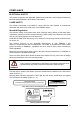
COMPLIANCE ELECTRICAL SAFETY This product conforms to the applicable requirements contained in the European Standard for electrical safety EN-60950-1 at the date of manufacture. LASER SAFETY The following information is provided to comply with the rules imposed by international authorities and refers to the correct use of the DS6400 reader. Standard Regulations This scanner utilizes a low-power laser diode.
The identification label is applied onto the bottom part of the scanner (Figure A, 2): DATALOGIC S.p.A. Via Candini, 2 40012 LIPPO DI CALDERARA DI RENO (BO) ITALY MANUFACTURED VOLT Amp. JANUARY 2002 15-30 DC 1.5-0.7 MODEL No. N2468 SERIAL No. This product conforms to the applicable requirements of 21CFR 1040 at the date of manufacture.
ITALIANO Informazione degli utenti ai sensi della Direttiva Europea 2002/96/EC L’apparecchiatura che riporta il simbolo del bidone barrato deve essere smaltita, alla fine della sua vita utile, separatamente dai rifiuti urbani.
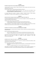
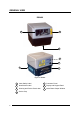
GENERAL VIEW DS6400 1 7 2 3 4 6 5 Figure A - DS6400 x 1 Laser Safety Label 5 Connector Panel 2 Identification Label 6 Display and Keypad Panel 3 Warning and Device Class Label 7 Laser Beam Output Window 4 Service Cap
DS6400 1 2 Figure B - DS6400 Oscillating Mirror Version 1 Laser Safety Label 2 Laser Beam Output Window 5 1 4 3 2 Figure C - Display and Keypad Panel 1 Programming Keypad 4 Power On LED 2 TX Data LED 5 LCD Display 3 Phase On LED xi
1 2 3 Figure D - Connector Panel for Master/Slave Models 1 Main/Aux. Interface 25-pin D-Sub male connector 2 Lonworks 9-pin male connector 3 Lonworks 9-pin female connector 1 2 3 Figure E – Connector Panel for Ethernet Models 1 Main/Aux. Interface 26-pin D-Sub male connector 2 RJ45 modular connector for Ethernet Interface 3 Lonworks 9-pin female connector 1 2 3 Figure F – Connector Panel for DeviceNet Models 1 Main/Aux.
GUIDE TO INSTALLATION POINT-TO-POINT INSTALLATION The following can be used as a checklist to verify all the steps necessary to complete installation of the DS6400 scanner. 1) Read all information in the section “Safety Precautions” at the beginning of this manual. 2) Correctly mount the scanner using the bracket provided according to the information in par. 2.2.2 and position it at the correct reading distance according to your model as shown in par. 2.5 and par. 4.4.
MASTER/SLAVE LONWORKS INSTALLATION The following can be used as a checklist to verify all the steps necessary to complete installation of the DS6400 scanner in a Master/Slave Lonworks network. 1) Read all information in the section “Safety Precautions” at the beginning of this manual. 2) Correctly mount the scanner using the bracket provided according to the information in par. 2.2.2 and position it at the correct reading distance according to your model as shown in par. 4.4.
8) Optionally, perform the ASR Network Configuration procedure for system backup purposes (see par. 5.2.1). 9) Exit the configuration program and run your application. The installation is now complete.
xvi
INTRODUCTION 1 1 INTRODUCTION 1.1 PRODUCT DESCRIPTION The DS6400 is a high performance laser scanner in a complete range of industrial bar code readers offering an innovative and modular solution in terms of reading performance, connectivity and maintenance, in addition to a completely new hardware and software platform. The DS6400 has been specifically designed for simple installation, easy use and flexibility.
DS6400 1 Feature Benefit Modular solution with separated head and base and Step-AHeadTM feature • • • • Reading on pallets or big objects where a large reading distance / wide reading field are needed Reading parcels on conveyors Master working as a multiplexer on a high speed Lonworks bus • • • • • GENIUSTM Configurator SW • • • • Possibility to select the combination of head and base that best fits the needs of the application; Great scalability of the offer; Down time cost reduction, since the
INTRODUCTION 1 1.3 OSCILLATING MIRROR MODELS Oscillating mirror models are used when coverage of a large reading area is required, mainly in picket fence applications. The DS6400 scanner mounts a dedicated optic head with integrated oscillating mirror driven by a linear motor. The speed, the precision, the repeatability, and the reliability of this driving technology assure high level performance. The new oscillating mirror is completely software controlled and software programmable.
DS6400 1 The mirror can be deflected up to 40°. Oscillation with respect to the output window median axis is asymmetrical ( see figure below). 37.5 40° ° -2.5° 0° Figure 3 - Oscillating Mirror Maximum Aperture and Asymmetry By configuring the oscillating speed up to the maximum value of 19 Hz, raster emulation can be performed for reading fast moving objects. Hz 0-5 6-10 11-15 16-19 Max.
INTRODUCTION 1 These models provide higher scanning speed (1200 scans/sec) compared to standard models and the reading performance is not adversely effected by the oscillating mirror. The following example represents the selection of an angle of +10° for the bottom line and an angle of +20° for the top line (see figure below). +37.5° +27.5° +17.5° Figure 5 - Oscillating Mode Refer to par. 2.2.1 for details about oscillating mirror mounting. 1.
DS6400 1 1.
INSTALLATION 2 2 INSTALLATION To install the system follow the given procedure: • Select the mounting location for DS6400; • Mount the DS6400 scanner; • Position the scanner with respect of the barcode; • Proceed with system electrical connection; • Install the Genius™ program on the PC and configure the scanner; • Set the Flash™ dynamic focus by means of the Genius™ software tool.
DS6400 2 2.2 MECHANICAL MOUNTING 2.2.1 Mounting the Scanner The DS6400 reader can be positioned and installed in the best way possible as a result of the Step-a-Head™ feature. Thanks to the separation between Head and Base, you can modify the orientation of the decoder base, and therefore display-keypad and connector panels, while keeping the optic head in the correct reading position.
INSTALLATION 2 The following diagrams give the overall dimensions of the reader standard model, oscillating mirror model and mounting brackets. They may be used for their installation. Refer to par. 2.4 for correct positioning of the scanner with respect to the code passage zone. 30 1.18 60 2.36 16.5 0.65 85 3.34 74 2.85 99 3.90 30 1.18 76 2.99 113 4.45 mm inch 110 4.33 Figure 8 - DS6400 Overall Dimensions 42 1.65 10 0.4 4 0.15 50 82 1.96 3.22 82 3.22 25 50 1.96 0.98 20 18 0.78 0.
DS6400 60 2.36 30 1.18 2 16.5 0.65 99 3.90 63.5 2.50 104.5 4.11 85 3.35 69 2.72 113 4.45 114 4.48 102 4.01 110.3 4.34 56 2.20 mm inch 180 7.08 Figure 10 - DS6400 Oscillating Mirror Model Overall Dimensions 42 1.65 22 0.86 4 0.15 35 1.37 5.11 130 82 3.22 50 1.96 20 0.78 50 1.96 25 0.98 18 0.71 10 0.4 Ø4.1 0.16 R1 11 0.43 14 0.55 50 1.96 72 2.83 100 3.93 R5 11 0.43 14 0.55 75 2.95 R22 36 1.41 R36 mm inch .
INSTALLATION 2.2.2 2 Mounting the Scanner with Accessories The following accessories allow installing the DS6400 reader in the most suitable position for your network layout: - ST-237 mounting bracket; - ST-210 mounting bracket; - FBK-6000 fast bracket.
DS6400 2 The FBK-6000 is a fast bracket kit allowing a quick and easy mounting of the scanner on either the ST-210 or the ST-237 brackets. First, it is necessary to fix the FBK-6000 to the DS6400 scanner by means of the mounting screws: Figure 14 – Mounting the FBK-6000 on the Scanner Then, attach the assembly to the mounting bracket by slipping the hook into the bracket hole.
INSTALLATION 2 2.
DS6400 2 The table below gives the pinout of the C-BOX 100 terminal block connectors.
INSTALLATION 2.3.1 2 Main/Aux. Serial Interface and I/O Connector The DS6400 master/slave model is equipped with a 25-pin male D-sub connector for connection to the host computer, power supply and input/output signals. The DS6400 fieldbus models (Ethernet, DeviceNet, Profibus) adopt a 26-pin male connector instead of the 25-pin one.
DS6400 2 Main Interface The main serial interface is compatible with the following electrical standards: RS232 RS485 full-duplex RS485 half-duplex (20 mA current loop) The 20 mA Current Loop interface is available by using the C-BOX 100 with the optional INT-30 accessory installed in it. The scanner communicates to the C-BOX 100 through the RS232 interface and the INT-30 converts the signals. The main serial interface type and its relative parameters (baud rate, data bits, etc.
INSTALLATION 2 RS485 Full-Duplex Interface The RS485 full-duplex interface is used for non-polled communication protocols in point-to-point connections over longer distances than those acceptable for RS232 communications or in electrically noisy environments. The overall maximum cable length should not exceed 1200 m (3937 ft).
DS6400 2 RS485 Half-Duplex Interface The RS485 half-duplex interface can be used for multidrop connections with a Datalogic multiplexer or it can also be used for a master/slave layout. The overall maximum cable length should not exceed 1200 m (3937 ft).
INSTALLATION 2 Auxiliary Interface The auxiliary serial interface is equipped with RS232 full-duplex interface connections. The interface type is exclusive and is selectable through the Genius™ configuration program. The overall maximum cable length should not exceed 15 m (50 ft).
DS6400 2 Inputs The inputs of the reader are on the 25-pin and 26-pin connector (Figure D, 1 and Figure E, 1) of the DS6400. These inputs are called EXT_TRIG/PS, IN2/ENC, IN3 and IN4.
INSTALLATION 2 DS6400 EXTERNAL TRIGGER/ENCODER Vext A/B + 5V ~ V - + ~ B/A Ground Figure 25 - NPN Command Input Connection using External Power EXTERNAL TRIGGER/ENCODER DS6400 VS A/B + 5V ~ + V - ~ B/A GND Ground Figure 26 - NPN Command Input Connection using Scanner Power Vext DS6400 EXTERNAL DEVICE V IN3A + 5V ~ + - ~ Ground Vext V IN4A + 5V ~ + ~ - INREF Ground Figure 27 - IN3/IN4 PNP Input Command using External Power 21
DS6400 2 DS6400 EXTERNAL DEVICE VS INREF + 5V ~ + V - ~ IN3A Ground EXTERNAL DEVICE + 5V ~ + V - ~ IN4A GND Ground Figure 28 - IN3/IN4 NPN Input Command using Scanner Power Input devices can be supplied by either scanner power (VS and GND) or external power supplies (Vext). Electrical isolation between the input command logic and the scanner is maintained when powering the input devices from an external supply voltage (Vext).
INSTALLATION 2 By default, OUT1 is associated with COMPLETE READ event, which activates when the code has been read correctly. In case the reader has been programmed to read several codes within the same reading phase, the event activates when all codes have been read. OUT2 is associated with NO READ event, which activates when no code has been read. OUT3 is associated with NONE, which means that the output is always in Line State.
DS6400 2 DS6400 USER INTERFACE Vext 100 Vdc max A B Figure 30 – Output 3 Interface The command signal is filtered and generates a delay of about 50 µs for OUT1 and OUT2 and 1 ms for OUT3. 2.3.2 Lonworks Connectors Do not connect an RS232 port to the 9-pin Lonworks Connector. This may damage your Laptop PC. CAUTION The local network used by DS6400 exploits a Lonworks standard communication system requiring only two wires (polarity insensitive) to enable a connection.
INSTALLATION 2 DS6400 9-pin Lonworks connector pinout Pin 1 9 2 6 3 4 5 7 8 Name CHASSIS VS GND VS_I/O Ref_I/O SYS_ENC_I/O SYS_I/O LON A LON B Function cable shield internally connected by capacitor to chassis Supply voltage - positive pin Supply voltage - negative pin Supply voltage of I/O circuit Reference voltage of I/O circuit System signal System signal Lonworks line (polarity insensitive) Lonworks line (polarity insensitive) Network Termination When building a Lonworks system the network must be
DS6400 2 Lonworks Interface The Lonworks network is used for both input and output connection to build a multi-sided or omni-station system connecting several readers. The DS6400 master usually employs the 9-pin female connector for output connection to the first slave, while the 9-pin male one is terminated by inserting the BTK6000 terminator (see par. 2.7.2 for details). If creating a T network configuration, it is necessary to use both connectors to create the double branch line of slave readers.
INSTALLATION 2 The diagram below represents the termination of a DS6400-XXX-010 working as master by means of the BTK-6000 terminator. BTK-6000 Female Side Master VS 9 9 VS_I/O 6 6 LON A 7 7 LON B 8 8 GND 2 2 REF_I/O 3 3 T = male connector = female connector Figure 35 – DS6400-XXX-010 Master Termination The diagram below represents the termination of a DS6400-XXX-010 working as slave by means of the BTK-6000 terminator.
DS6400 2 2.3.3 Ethernet Connector This connector is only available for DS6400 Ethernet models and allows the Ethernet connection between the host and the reader. 8 1 Figure 38 – Cable RJ45 Male Modular Connector 1 8 Figure 39 – DS6400 RJ45 Female Modular Connector This interface and the connector pinout (see the following table) are IEEE 802.3 10 BaseT and IEEE 802.3u 100 Base Tx compliant. RJ45 Modular Jack Pinout Pin 1 2 3 6 4, 5, 7, 8 Name TX + TX RX + RX N.C.
INSTALLATION 2 Ethernet Interface The Ethernet interface (NIC) can be used for TCP/IP communication with remote or local host computer by connecting the scanner to a LAN as well as with a host PC directly connected to the scanner. The following is an example of a connection to a LAN through a Hub using a straight through cable: HUB / SWITCH DS6400 TX+ 1 1 TX- 2 2 RX+ 3 3 n. c. 4 4 n. c. 5 5 RX- 6 6 n. c. 7 7 n. c. 8 8 n. c.
DS6400 2 2.3.4 DeviceNet Connector When using DeviceNet, the Main serial interface is disabled and must not be physically connected.
INSTALLATION 2.3.5 2 Profibus Connector The 9-pin Profibus female connector (white) is only available in the DS6400 Profibus model and allows connection between the host and the reader: 1 5 9 6 Figure 43 - Profibus 9-pin Female Connector DS6400 9-pin Profibus connector pinout Pin 1 2 3 4 5 6 7 8 9 * ** Name Shield* Free B-LINE (RxD/TxD-P) CNTR-P** DGND +5 V Free A-LINE (RxD/TxD-N) CNTR-N** Function Shield, Protective Ground resp.
DS6400 2 2.3.6 Power Supply The supply voltage of a single scanner must be between 15 and 30 VDC. Datalogic strongly recommends a minimum 24 VDC supply voltage when using a master/slave configuration. The power consumption of the different DS6400 models is slightly different. In particular, when connecting several DS6400 readers in a master/slave connection, the typical power consumption for each scanner is 15 W. There is a power peak of about 20 W lasting 5..10 seconds caused by the motor starting.
INSTALLATION 2 How To Build A Simple Interface Test Cable: The following wiring diagram shows a simple test cable including power, external (push-button) trigger and PC RS232 COM port connections. 25-pin D-sub female 9-pin D-sub female 21 TXAUX 2 RX 20 RXAUX 3 TX 5 GND 23 GND PC 13 VS 25 GND DS6400 9 VS 18 EXT TRIG A 19 EXT TRIG B Power Supply VS (15 – 30 VDC) Power GND Trigger Test Cable for DS6400 2.
DS6400 2 The Skew angle is represented by the value S in Figure 46. Position the reader to assure at least 10° for the Skew angle. This avoids the direct reflection of the laser light emitted by the scanner. For oscillating mirror models, this angle refers to the most inclined or external laser line, so that all other laser lines assure more than 10° Skew. S Figure 46 - "Skew" Angle The Tilt angle is represented by the value T in Figure 47.
INSTALLATION 2 2.6 TYPICAL INSTALLATIONS 2.6.1 Standard Installation The DS6400 scanner is mounted on the ST-237 106° mounting bracket (see Figure 9) which guarantees a built-in Skew angle (S in the figure below) of 16° with respect to the frame plane (typically the Skew angle should be between 10° - 20°). This avoids the direct reflection of the laser light emitted by the scanner.
DS6400 2 ATTENTION If using the “45° Skew” installation, the scanner reading performance is not guaranteed to match that measured for the standard installation with Skew angle between 10° - 20° (see reading diagrams in par. 4.4.1). The ST-210 mounting bracket is an accessory of the DS6400 standard model available in the US-60 kit (890001020). NOTE 2.
INSTALLATION 2 Master/Slave Models When On-Line operating mode is used, the reader is activated by an External Trigger (photoelectric sensor) when the object enters its reading zone. In the following case, the signal is passed to the DS6400 by the C-BOX 100, which also supplies the system. M/S CAB-600X C-BOX 100 Local Host Presence Sensor* PG6000 * P.S. (Presence Sensor) connected to External Trigger/PS input.
DS6400 2 2.7.2 Pass Through When Pass Through is activated on the Auxiliary interface, the DS6400 reader (all models) can be integrated in a network consisting of different scanners not provided with a Lonworks interface. This connection mode allows two or more devices to be connected to a single external serial interface. The DS6400 transmits the messages received by its auxiliary interface (RS232 only) onto its main interface.
INSTALLATION 2 Remote Host P.S.* P.S.* Gryphon DS4600A < < EN T CAB-601X C-BOX 100 AUX DS4600A < < DS6400 EN T Fieldbus Network C-BOX 100 C-BOX 100 P.S.* 2 1 2 1 PWR-120 1 * Main Serial Interface 2 Auxiliary Serial Interface P.S. (Presence Sensor) connected to External Trigger/PS input. Figure 53 – Pass Through Connection for Fieldbus Models 2.7.
DS6400 2 DS6400- Master C-BOX 100 AUX CAB-600X 1 EN MAIN P.S.* 2 < < T DS4600A Slave 1 Local Host 1 C-BOX 100 2 < DS4600A Slave 2 EN T < PWR-120 C-BOX 100 1 1 * 2 Main Serial Interface Auxiliary Serial Interface P.S. (Presence Sensor) connected to External Trigger/PS input. Figure 54 – RS232 Master/Slave for DS6400 Master/Slave Models Remote Host Fieldbus Network DS6400 Master CAB-601X AUX DS4600A Slave 2 C-BOX 100 2 < EN T P.S.
INSTALLATION 2.7.4 2 Multiplexer The Multiplexer connection is used to integrate a DS6400 slave reader in a Multidrop network consisting of different scanners not provided with a Lonworks interface. Each scanner is connected half-duplex main interface. Multiplexer (MX4000) with the RS485 P.S.* P.S.* < DS4600A < DS6400 a DS4600A PWR-120 EN T < < EN T P.S.* to CAB-600X C-BOX 100 C-BOX 100 #31 #1 C-BOX 100 MX4000 1 #0 Local Host 1 * RS485 HD Main Interface P.S.
DS6400 2 2.7.5 Local Lonworks Network A local Lonworks network allows logically connecting a DS6400 master reader with up to 31 DS6400 slaves. Actually, the maximum number of readers to be employed in the network depends on the system operating conditions; that is adopted operating mode and amount of data stream.
INSTALLATION 2 Small Synchronized Network When building a small local Lonworks network (less than 10 scanners), the DS6400 master reader must be connected to a local host computer or a C-BOX 100 by means of a CAB-60XX cable connected to the 25-pin or 26-pin D-sub male connector. The master reader connects to the first slave reader of the system through the local Lonworks 9-pin female connector.
DS6400 2 The following image shows a system consisting of six readers where: • the system is powered by the PWR-240 • the master and all slaves are connected together through the CAB-610X cables • the external signals (trigger, encoder, serial to host, etc.) are connected to the master through the C-BOX 100 • one or more slaves are connected through CAB-63XX.
INSTALLATION 2 Large Synchronized Network When building a large local Lonworks network (more than 10 scanners), an SC6000 Controller must be used together with a PWO power supply/junction box unit. In this case the SC6000 unit acts as the system master and is connected to the host through one of its interfaces. All scanners act as slaves and are connected to the SC6000 through the PWO power supply/junction box.
DS6400 2 Multidata Network In this layout, one master and up to 7 DS6400 slave readers have their own P.S. and therefore multiple reading phases. Each P.S. is connected through a C-BOX 100, which in turn is connected to its relative scanner through a CAB-60XX cable. The master sends all the individual messages collected from the Lonworks interface as well as its own to the Local Host through its C-BOX 100.
INSTALLATION 2.7.6 2 Fieldbus Network The Fieldbus Ethernet model offers connectivity without any converter or adapter needed. The DS6400 master Fieldbus communicates with a remote host (for ex. remote PC connected via Internet) by means of a cable connected to the Fieldbus connector provided. It can be activated by a signal generated by the remote Host or by a physical presence sensor. The external signals (trigger, encoder) are connected to the master through the C-BOX 100.
DS6400 2 2.8 FLASH™ DYNAMIC FOCUS The DS6400 has an innovative linear motor designed to control the focus position of the scanner via software. This dynamic system, called FLASHTM, is able to move the focus position rail to rail, from the minimum position to the maximum position. The FLASHTM functionalities are programmed via the GENIUS™ tool (refer to the GENIUS™ Help On-Line for details) and can operate in the following modes: • • • • Fixed Mode Continuous Mode Triggered Mode D-Flash™ Mode 2.8.
INSTALLATION 2.8.3 2 Triggered Mode In Triggered mode, the focus position can be set depending on the received external input (photocell, barrier, serial message…). This mode represents the most traditional Flash™ function, since it requires photocells, barriers or a dedicated interface to the Host (PC or PLC). The excellent performance of the DS6400 optic platform allows covering an area of 80 x 80 cm containing a 38 mm/15 mils resolution code by using one photocell only.
DS6400 2 2.
INSTALLATION 2.9.2 2 Test Mode Test Mode is particularly advised during the installation phase, since it causes the reader to be continuously activated allowing to verify its reading features and its reading position with respect to the barcode. To enter the Test Mode submenu and configure the scanner follow the given procedure: 1) Press and hold both the ▲ (up arrow) and ▼ (down arrow) keys for about 2 seconds to enter the Main menu.
DS6400 3 3 SOFTWARE CONFIGURATION 3.1 GENIUS™ INSTALLATION Genius™ is a new Datalogic scanner configuration tool providing several important advantages: • Wizard approach for low skilled users; • Multi-language version; • Defined configuration directly stored in the reader; • Communication protocol independent from the physical interface allowing to consider the reader as a remote object to be configured and monitored.
SOFTWARE CONFIGURATION 3 After defining the parameter values the following window appears allowing to complete the reader configuration as follows: - Saving the configuration to disk; - Switching to Advanced mode; - Sending the configuration to the scanner. Figure 67 - Genius™ Wizard Closing Window Test Operating Mode This operating mode is not available when DS6400 works as slave.
DS6400 3 On Line Operating Mode Figure 69 - On Line Mode Selection This operating mode requires the reader to be connected to an external Presence Sensor using EXT TRIG/PS A and EXT TRIG/PS B inputs. During the active phase of the presence sensor, the DS6400 reader tries to acquire and correctly decode the code. In case the decoding phase is successful, the barcode characters are transmitted on the serial interface. Otherwise, a no read message is sent.
SOFTWARE CONFIGURATION 3.2.2 3 Genius™ Network Setup Through Master The Network Setup allows configuring your Local Lonworks Network through the Master using Genius™. Three different procedures are available to define the number of network slave scanners, their label and address according to two main conditions: Condition Available Procedure Feature Unknown Slave Addresses Net-Autoset automatically assigns random addresses to slave or Stand Alone scanners.
DS6400 3 The following dialog box appears asking whether to send the configuration to the Master or not: icon available on the Toolbar to make the 2. Click the "Yes" button, then click on the “Devices” area appear next to the Parameter Explorer window. By repeatedly clicking the icon this area will be displayed or hidden.
SOFTWARE CONFIGURATION 3 3. Then, proceed with the network setup by using one of the icons available on the Tool Bar according to the procedure to follow: = Net-Autoset procedure = Network Wizard procedure = Express Network Setup procedure Net-Autoset This procedure is to be used when all scanner addresses and labels are unknown (typically when configuring the network for the first time or whenever a network reconfiguration is required).
DS6400 3 Network Wizard Before performing this procedure, a Lonworks address must be assigned to each slave scanner. The most practical method is through the Net-Autoset procedure. See par. 3.2.3 for alternative address assignment methods. Once all addresses have been assigned, the Network Wizard is to be used when one or more scanner addresses and labels need to be modified. 1. Click on the button to open the Network Wizard dialog box: a.
SOFTWARE CONFIGURATION 3 2. If desired, select a slave scanner within the "Current Devices" area and click on the icon (or select the "Show Device" option from the right-click menu) to make the dialog box appear as follows: • • The "Show Device" option is particularly useful after the Net-Autoset procedure or whenever it is necessary to know which address is assigned to a specific slave scanner.
DS6400 3 3.2.3 Alternative Slave Address Assignment As alternatives to Network Setup through the Master, each Slave scanner can be assigned an address through the following methods: • address setting through the Local Device Network Settings item in the Device Menu with the slave scanner connected to Genius™ • manual address setting through slave scanner keyboard (see par. 2.9.1 for details). 3.
SOFTWARE CONFIGURATION 3 3.4 PARAMETER DEFAULT VALUES The following table contains the list of the factory default settings for the DS6400. Genius™ also allows checking the parameter default values by selecting the "Compare parameters" option available in the Tools menu and comparing the current scanner configuration to the default one.
DS6400 3 Parameter Reading Parameters Beam Shutter Overflow Start Ratio Overflow Stop Ratio Reading Mode Reading Condition Reconstruction Parameters Enabled Stacked Code Extended Min Match Position Tolerance Duration Tolerance Min Start/Stop Number Inter Char Gap Addon Overflow Ratio Scan Line Amplitude Amplitude Settings Enable Flash Flash Mode Fixed Distance Data Communication Settings Host Application Protocol Type Data Format Header TX Start Termination After No Read Message Message Tx Trigger Selectio
SOFTWARE CONFIGURATION Parameter Parameters Data Bits Stop Bits Auxiliary Serial Port Data Tx Heartbeat Pass Through Parameters Baud Rate Parity Data Bits Stop Bits Digital I/O Setting Digital Input Lines Setting Debouncing For Input 1, 3 and 4 Debouncing For Input 2 Input 1 Active Level Overridden by Op. Mode Input 2 Active Level Overridden by Op. Mode Input 3 Active Level Overridden by Op. Mode Input 4 Active Level Overridden by Op.
DS6400 3 Parameter Diagnostics PackTrack Debug Message Tx Enable Statistics 64 Default Setting Disabled (unchecked) Unchecked Disabled (unchecked)
READING FEATURES 4 4 READING FEATURES 4.1 ADVANCED CODE RECONSTRUCTION (ACR™ 4) The traditional way of barcode reading could be called “Linear Reading”. In this case, the laser beam crosses the barcode symbol from its beginning to its end as shown in the following figure: Laser Beam Figure 74 – Linear Reading In Advanced Code Reconstruction mode it is no longer necessary for the laser beam to cross the label from the start to the end.
DS6400 4 The decoder will be able to read the label + α max and - α max as shown in the following figure: with a tilt angle between 0° OK OK No Read No Read No Read Conveyor -α +α OK OK OK Laser Beam Figure 77 – Reading Zones with α Max 4.2 PACKTRACK™ PackTrack™ is a patented operating mode for Datalogic Omni-Directional Reading Stations used to read and correctly assign codes read on different packs when placed in the scanner Reading Area at the same time.
READING FEATURES 4 For correct functioning, the PackTrack™ operating mode requires a calibration just after the installation of the scanners. This operation is absolutely necessary to make the scanner recognize its position in space. Thus, a fixed reference system is required.
DS6400 4 4.2.1 PackTrack™ Calibration for DS6400 By means of the Genius™ software tool SPY, the user can perform PackTrack™ calibration. Select the “SPY” option from the Tools menu or click on the related icon on the Genius™ toolbar to open the following dialog box: Note: When selecting a slave scanner through the Master, click on the slave to calibrate in the Devices window, then click the SPY icon.
READING FEATURES 4 By selecting the “PackTrack Calibration” option a further dialog box appears allowing to start calibration: Position 1 Position 2 Position 3 Figure 82 – Performing the PackTrack™ Calibration 1. Place the code at the desired position on the scan line (i.e. Position 1) 2. Measure the X, Y and Z coordinates relative to the center of the code and enter them into the corresponding edit boxes. 3. Press the Calibrate button for Position 1 to start the calibration. 4.
DS6400 4 4.2.2 PackTrack™ Calibration for DS6400 Oscillating Mirror Models The DS6400 oscillating mirror models can be used in PackTrack™ operating mode only when the scanner is mounted so that the scan line is parallel to the conveyor direction as shown in the following figure: Conveyor Direction Scan Line Figure 83 – Oscillating Mirror Models in PackTrack™ Mode PackTrack™ Calibration must be made while the scanning plane is perpendicular to the conveyor plane and fixed (not oscillating). 4.
READING FEATURES Conveyor Speed (m/s) 0.25 0.30 Code 39 0.33 Code Resolution 0.38 (mm) 0.50 0.72 1.00 4 0.5 9 10 11 12 15 20 27 Minimum Code Height for ACR Reading (mm) 45° 30° 1 1.5 2 2.5 3 0.5 1 1.5 2 2.5 10 12 14 16 17 6 7 9 10 12 11 13 15 17 18 7 8 9 11 12 12 13 15 17 19 7 8 10 11 13 13 14 16 18 20 8 9 10 12 13 16 17 18 20 22 10 10 11 13 14 21 22 23 24 26 13 13 14 15 17 28 29 30 31 32 17 17 18 19 20 3 13 14 14 15 16 18 21 Ratio 3:1; Interdigit = Module Size Table 2 Conveyor Speed (m/s) 0.25 0.
DS6400 4 4.4 READING DIAGRAMS The reading diagram given below illustrates the convention used to calculate the minimum and maximum reading distance for barcodes. This procedure allows calculating the reading distance of your scanner when working with a focus different from the one displayed in the reading diagrams given in par. 4.4.1 and par. 4.4.2.
READING FEATURES 4.4.1 4 DS6400 Standard Model DS6400-100-0XX - Resolution: 0.20 mm/8 mils The diagram shows a global reading area, which includes all possible focus positions, and the reading area obtained for the DS6400-100-0XX operating with focus position = 65 cm and barcode density of 0.20 mm (8 mils). It is possible to obtain the minimum and maximum distance values by referring to the radial distance curves displayed in Figure 86.
DS6400 4 The curves show the minimum and maximum radial distance. Reading distance (in) (cm) 40 100 38 95 36 90 34 85 32 80 30 75 28 70 26 65 24 60 22 55 20 50 18 45 16 40 0 0 Max. Reading Distance Min. Reading Distance 40 16 45 18 50 55 60 20 22 24 65 26 70 28 75 80 30 32 85 90 95 100 34 36 38 40 (cm) (in) Focus Distance Figure 86 – Standard Model 0.
READING FEATURES 4 DS6400-100-0XX - Resolution: 0.25 mm/10 mils The diagram shows a global reading area, which includes all possible focus positions, and the reading area obtained for the DS6400-100-0XX operating with focus position = 90 cm and barcode density of 0.25 mm (10 mils). It is possible to obtain the minimum and maximum distance values by referring to the radial distance curves displayed in Figure 88.
DS6400 4 The curves show the minimum and maximum radial distance. Reading distance (in) (cm) 48 120 46 115 44 110 42 105 40 100 38 95 36 90 34 85 32 80 30 75 28 70 26 65 24 60 22 55 20 50 0 Max. Reading Distance Min. Reading Distance 45 18 50 20 55 22 60 65 24 26 70 28 75 30 80 32 85 34 90 95 100 105 110 115 (cm) 36 38 40 42 44 46 (in) Focus Distance Figure 88 – Standard Model 0.
READING FEATURES 4 DS6400-100-0XX - Resolution: 0.30 mm/12 mils The diagram shows a global reading area, which includes all possible focus positions, and the reading area obtained for the DS6400-100-0XX operating with focus position = 110 cm and barcode density of 0.30 mm (12 mils). It is possible to obtain the minimum and maximum distance values by referring to the radial distance curves displayed in Figure 90.
DS6400 4 The curves show the minimum and maximum radial distance. Reading distance (in) (cm) 72 180 68 170 64 160 60 150 56 140 52 130 Max. Reading Distance 48 120 44 110 40 100 36 90 32 80 28 70 24 60 20 50 16 40 0 Min. Reading Distance 55 22 60 24 65 26 70 75 28 30 80 32 85 34 90 36 95 100 105 110 115 120 125 130 (cm) 38 40 42 44 46 48 50 52 (in) Focus Distance Figure 90 – Standard Model 0.
READING FEATURES 4 DS6400-100-0XX - Resolution: 0.38 mm/15 mils The diagram shows a global reading area, which includes all possible focus positions, and the reading area obtained for the DS6400-100-0XX operating with focus position = 140 cm and barcode density of 0.38 mm (15 mils). It is possible to obtain the minimum and maximum distance values by referring to the radial distance curves displayed in Figure 92.
DS6400 4 The curves show the minimum and maximum radial distance. Reading distance (in) (cm) 72 180 68 170 64 160 Max. Reading Distance 60 150 56 140 52 130 48 120 44 110 40 100 36 90 32 80 28 70 24 60 20 50 16 40 0 Min. Reading Distance 40 50 16 20 60 24 70 28 80 90 100 110 120 130 140 150 160 170 180 (cm) 32 36 40 44 48 52 56 60 (in) 64 68 72 Focus Distance Figure 92 – Standard Model 0.
READING FEATURES 4 DS6400-100-0XX - Resolution: 0.50 mm/20 mils The diagram shows a global reading area, which includes all possible focus positions, and the reading area obtained for the DS6400-100-0XX operating with focus position = 120 cm and barcode density of 0.50 mm (20 mils). It is possible to obtain the minimum and maximum distance values by referring to the radial distance curves displayed in Figure 94.
DS6400 4 The curves show the minimum and maximum radial distance. Reading distance (in) (cm) 80 200 76 190 72 180 68 170 64 160 Max. Reading Distance 60 150 56 140 52 130 48 120 44 110 40 100 36 90 32 80 28 70 24 60 20 50 0 Min. Reading Distance 40 16 50 20 60 24 70 28 80 90 100 110 120 130 140 150 160 170 180 (cm) 32 36 40 44 48 52 56 60 (in) 64 68 72 Focus Distance Figure 94 – Standard Model 0.
READING FEATURES 4.4.2 4 DS6400 Oscillating Mirror Model DS6400-105-0XX - Resolution: 0.20 mm/8 mils The diagram shows a global reading area, which includes all possible focus positions, and the reading area obtained for the DS6400-105-0XX operating with focus position = 60 cm and barcode density of 0.20 mm (8 mils). It is possible to obtain the minimum and maximum distance values by referring to the radial distance curves displayed in Figure 96.
DS6400 4 The curves show the minimum and maximum radial distance. Reading distance (in) (cm) 36 90 34 85 32 80 30 75 28 70 26 65 24 60 22 55 20 50 18 45 16 Max. Reading Distance Min. Reading Distance 40 0 0 40 16 45 18 50 55 60 65 20 22 24 26 70 28 75 80 85 30 32 90 34 36 (cm) (in) Focus Distance Figure 96 - Oscillating Mirror Model 0.
READING FEATURES 4 DS6400-105-0XX - Resolution: 0.25 mm/10 mils The diagram shows a global reading area, which includes all possible focus positions, and the reading area obtained for the DS6400-105-0XX operating with focus position = 95 cm and barcode density of 0.25 mm (10 mils). It is possible to obtain the minimum and maximum distance values by referring to the radial distance curves displayed in Figure 98.
DS6400 4 The curves show the minimum and maximum radial distance. Reading distance (in) (cm) 46 115 44 110 42 105 40 100 38 36 95 Max. Reading Distance 90 34 85 32 80 30 75 28 70 26 65 24 60 22 55 20 50 18 45 0 Min. Reading Distance 45 18 50 20 55 22 60 65 24 26 70 28 75 30 80 32 85 34 90 95 36 38 100 105 110 115 (cm) 40 42 44 46 (in) Focus Distance Figure 98 - Oscillating Mirror Model 0.
READING FEATURES 4 DS6400-105-0XX - Resolution: 0.30 mm/12 mils The diagram shows a global reading area, which includes all possible focus positions, and the reading area obtained for the DS6400-105-0XX operating with focus position = 110 cm and barcode density of 0.30 mm (12 mils). It is possible to obtain the minimum and maximum distance values by referring to the radial distance curves displayed in Figure 100.
DS6400 4 The curves show the minimum and maximum radial distance. Reading distance (in) (cm) 68 170 64 160 60 150 56 140 52 130 48 120 Max. Reading Distance 44 110 40 100 36 90 32 80 28 70 24 60 20 50 16 40 0 Min. Reading Distance 50 20 55 22 60 24 65 70 26 28 75 30 80 32 85 34 90 36 95 100 105 110 115 120 (cm) 38 40 42 (in) 44 46 48 Focus Distance Figure 100 - Oscillating Mirror Model 0.
READING FEATURES 4 DS6400-105-0XX - Resolution: 0.38 mm/15 mils The diagram shows a global reading area, which includes all possible focus positions, and the reading area obtained for the DS6400-105-0XX operating with focus position = 115 cm and barcode density of 0.38 mm (15 mils). It is possible to obtain the minimum and maximum distance values by referring to the radial distance curves displayed in Figure 102.
DS6400 4 The curves show the minimum and maximum radial distance. Reading distance (in) (cm) 72 180 68 170 64 160 Max. Reading Distance 60 150 56 140 52 130 48 120 44 110 40 100 36 90 32 80 28 70 24 60 20 50 16 Min. Reading Distance 40 0 40 16 50 20 60 24 70 28 80 90 100 110 120 130 140 150 160 170 180 (cm) 32 36 40 44 48 52 56 60 (in) 64 68 72 Focus Distance Figure 102 - Oscillating Mirror Model 0.
READING FEATURES 4 DS6400-105-0XX - Resolution: 0.50 mm/20 mils The diagram shows a global reading area, which includes all possible focus positions, and the reading area obtained for the DS6400-105-0XX operating with focus position = 115 cm and barcode density of 0.50 mm (20 mils). It is possible to obtain the minimum and maximum distance values by referring to the radial distance curves displayed in Figure 104.
DS6400 4 The curves show the minimum and maximum radial distance. Reading distance (in) (cm) 76 190 72 180 68 170 64 160 Max. Reading Distance 60 150 56 140 52 130 48 120 44 110 40 100 36 90 32 80 28 70 24 Min. Reading Distance 60 20 50 16 40 0 40 16 50 20 60 24 70 28 80 90 100 110 120 130 140 150 160 170 180 (cm) 32 36 40 44 48 52 56 60 (in) 64 68 72 Focus Distance Figure 104 - Oscillating Mirror Model 0.
MAINTENANCE 5 5 MAINTENANCE 5.1 CLEANING Clean the laser beam output window (Figure A, 7) periodically for correct operation of the scanner. Dust, dirt, etc. on the window may alter the reading performance. Repeat the operation frequently in particularly dirty environments. Use soft material and alcohol to clean the window and avoid any abrasive substances. Clean the window of the DS6400 when the scanner is turned off or at least when the laser beam is not active. WARNING 5.
DS6400 5 5.2.2 Scanner Replacement Procedure The ASR procedure requires replacing one scanner at a time. NOTE Slave 1. Power down the entire system. 2. Replace the Slave scanner with a new one (default settings). 3. Power up the system and wait for initialization. Master 1. Load the saved configuration from file (.ddc) to the new Master. 2. Power down the entire system. 3. Replace the Master scanner with the new one. 4. Power up the system and wait for initialization.
TROUBLESHOOTING 6 6 TROUBLESHOOTING NOTE Before contacting your local Datalogic office or Datalogic Partner or ARC, it is suggested to save the device configuration to a *.ddc file by means of the Genius™ software configuration program and check the device exact model and serial number. TROUBLESHOOTING GUIDE Problem Power On: the “Power On” LED is not lit. On Line Mode: the Master’s “Phase On” LED is not lit (when external trigger activates).
DS6400 6 TROUBLESHOOTING GUIDE Problem On Line Mode and Serial On Line Mode: the reader does not respond correctly to the expected external signal end. Reading: it is not possible to read the target barcode (always returns No Read) Suggestion • In the Genius™ software configuration program select the OPERATING MODES folder and check the “Reading Phase Timeout” parameterization. • • • • • Communication: the device is not transmitting anything to • the host.
TROUBLESHOOTING 6 TROUBLESHOOTING GUIDE Problem Suggestion How do I obtain my units’ serial • The device serial number is printed on the device identification label that is affixed to the numbers? reader (Figure A, 2). • The serial number is also displayed when connecting the device through the Genius™ program. • Serial numbers consist of 9 characters: one letter, 2 numbers, another letter followed by 5 numbers.
DS6400 7 7 TECHNICAL FEATURES ELECTRICAL FEATURES (see note 1) Supply voltage Power consumption Communication Interfaces 15 to 30 Vdc 15 W typical 20 W Max.
TECHNICAL FEATURES 7 SOFTWARE FEATURES Readable codes Code selection Headers and Terminators Operating modes Configuration modes Parameter storage Interleaved 2/5 Code 39 standard Codabar Code 128 EAN128 Code 93 (Standard and Full ASCII) EAN/UPC (including Add-on 2 and Add-on 5) Up to 10 codes during one reading phase Transmitted messages can be personalized using up to 128-byte headers and 128-byte terminators On Line Automatic Test PackTrack™ Genius™ utility program Non-volatile internal FLASH ENVIR
GLOSSARY ACR™ 4 Each version of the base has the powerful code reconstruction technology (ACR™ 4). The new fourth generation ACR™ considerably increases the code reconstruction reading capability in the case of damaged or very tilted barcodes. Aperture Term used on the required CDRH warning labels to describe the laser exit window. Barcode A pattern of variable-width bars and spaces which represents numeric or alphanumeric data in machine-readable form.
Full Duplex Simultaneous, two-way, independent transmission in both directions. Half Duplex Transmission in either direction, but not simultaneously. Host A computer that serves other terminals in a network, providing services such as network control, database access, special programs, supervisory programs, or programming languages. Interface A shared boundary defined by common physical interconnection characteristics, signal characteristics and meanings of interchanged signals.
RS485 Interface that specifies the electrical characteristics of generators and receivers for use in balanced digital multipoint systems such as on a Multidrop line. Scanner A device that examines a printed pattern (barcode) and either passes the uninterpreted data to a decoder or decodes the data and passes it onto the Host system. Serial Port An I/O port used to connect a scanner to your computer, identifiable by a 9-pin or 25-pin connector. Signal An impulse or fluctuating electrical quantity (i.e.
INDEX A I Accessories; 6 ACR™ 4; 65 Inputs; 20 Installation; 7 45° Skew Installation; 35 Mounting the Scanner; 8 Mounting with Accessories; 11 Overall Dimensions; 9 Standard Installation; 35 Interfaces Auxiliary; 19 Ethernet; 29 Lonworks; 26 Main RS232; 16 Main RS485 Full Duplex; 17 Main RS485 Half Duplex; 18 Profibus; 31 C CE Compliance; viii Cleaning; 93 Connectors 25-pin connector; 15 26-pin connector; 15 DeviceNet; 30 Ethernet; 28 Lonworks; 24 Profibus; 31 D DeviceNet; 30 E K Electrical Connection
PackTrack™; 66 Parameter Explorer Window; 60 Parameter Groups Default Values; 61 Patents; vi Positioning; 33 Pitch Angle; 33 Skew Angle; 34 Tilt Angle; 34 Power Supply; viii; 32 Profibus; 31 R Reading Diagrams; 72 Oscillating Mirror Models; 83 Standard Models; 73 Reading Features; 65 Reference Documentation; vi S Services and Support; vi Small Synchronized Network; 43 Software Configuration; 52 T Technical Features; 98 Terminator; 25 Troubleshooting; 95 Typical Layouts; 36 Fieldbus Network; 47 Local Lonwo
DECLARATION OF CONFORMITY 07 Datalogic Automation S.r.l. Via S.
www.automation.datalogic.