
- Datalogic Laser Scanner Reference Manual

DS6400
2
DS6400
USER INTERFACE
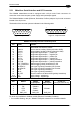
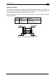
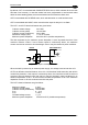
Vext
100 Vdc max
A
B
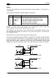
Figure 30 – Output 3 Interface
The command signal is filtered and generates a delay of about 50 µs for OUT1 and OUT2
and 1 ms for OUT3.
2.3.2 Lonworks Connectors
Do not connect an RS23
CAUTION
2 port to the 9-pin Lonworks Connector. This may
damage your Laptop PC.
The local network used by DS6400 exploits a Lonworks standard communication system
requiring only two wires (polarity insensitive) to enable a connection. The connector also
rovides a positive and a negative supplying wire. In this way, all the slave readers can be
the
h the cable.
he internal circuits generating the system signals are externally supplied by means of the
r. 2.7 for
etails). Anyway, for a correct system functioning it is suggested to use Datalogic cables and
ccessories and follow the description of the typical layout (see par. 2.7 for details).
p
powered by the master through the Datalogic standard cables.
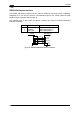
When working in applications requiring enhanced synchronization capabilities, the DS6400
master reader (output) transmits two system signals named Sys_I/O and Sys_Enc_I/O to
slave readers (input). For example, when working with applications requiring an encoder the
signal is received by the master and directly transmitted to the slaves throug
T
VS_I/O and REF_I/O pins and are isolated from the reader supply voltage.
The use of these system circuits is not required in all the operating modes (see pa
d
a
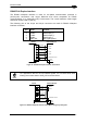
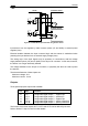
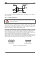
5
1
9
6
Female (all mode
1
5
6
9
ls)
Male (Master/Slave model)
Figure 31 – 9-pin Local Lonworks Connectors
24