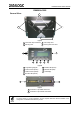
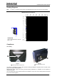
DX8200A-3002 QUICK GUIDE DX8200A-3002 General View: 1 2 2 3 4 Figure A 1 Laser Beam Output Windows 3 Laser Safety Label 2 Mounting Slots 4 Mounting Reference Label 7 1 2 4 3 5 6 Figure B 1 Programming Keypad 5 TX Data LED (Green) 2 Power On LED (Green) 6 Network LED (Red) 3 Phase On LED (Yellow) 7 LCD Display 4 Encoder LED (Yellow) 1 2 Figure C 1 Lonworks 17-pin Male Connector 2 Lonworks 17-pin Female Connector For further details on product installation, see the complete Refere
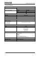
DX8200A-3002 QUICK GUIDE Technical Features: ELECTRICAL FEATURES Supply voltage Power consumption Communication Interfaces Auxiliary RS232 Other Lonworks 20 to 30 Vdc 30 W typical 35 W Max. (including startup current) Baud Rate 1200 to 115200 1.
DX8200A-3002 QUICK GUIDE ENVIRONMENTAL FEATURES Operating temperature Storage temperature Humidity Ambient light immunity Vibration resistance: EN 60068-2-6 2 hours on each axis 0° to +50 °C (+32° to +122 °F) -20° to +70 °C (-4° to +158 °F) 90% non condensing 20000 lux Frequency range from 5 to 150 Hz; Constant displacement 3 mm pk-pk from 5 to 9 Hz; Constant acceleration 0.
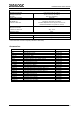
DX8200A-3002 QUICK GUIDE Electrical Connections: Two 17-pin connectors provide access to the scanner’s local Lonworks network used for both input and output connections to build a multi-sided or omni-station system. 17-pin Lonworks Connector Pinout Pin A1 A2 4 Name GND VS 1 CHASSIS 2 n.c.
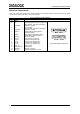
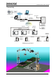
DX8200A-3002 QUICK GUIDE Connectivity: Host HUB ETHERNET CAB-SC6103 Cable SC6000 AUX VAC INPUT Power/Net CAB-SC6003 PWO CAB-SC6003 Extended I/O LONWORKS ENCODER BTK8500 Bus Return CAB-850x CAB-850x CAB-850x PS PS Aux CAB-850x up to 3 scanners per branch DX8200A-3002 DX8200A-3002 CAB-850x CAB-850x BTK8500 Bus Return DX8200A-3002 CAB-850x up to 4 scanners per branch DS8100A-3002 DS8100A-3002 DS8100A-3002 DS8100A-3002 DX8200A-3002 Typical Layout 5
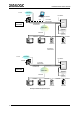
DX8200A-3002 QUICK GUIDE to Host ETHERNET SC6000 CAB-SC6103 AUX Working Controller VAC INPUT Power/Net CAB-SC6003 PWO CAB-SC6003 Extended I/O LONWORKS ENCODER CAB-850x CAB-850X CAB-850x DX8200A PS PS Aux DS8100A DS8100A DX8200A BTK8500 CAB-850x Redundancy CAB-PWO 03 ETHERNET to Host VAC INPUT SC6000 Power/Net CAB-SC6003 PWO CAB-SC6003 Extended I/O Protecting Controller LONWORKS ENCODER CAB-850x CAB-850X CAB-850x DX8200A PS PS Aux DX8200A CAB-850x DS8100A Example of Redundan
DX8200A-3002 QUICK GUIDE Example of Redundant System 7
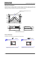
DX8200A-3002 QUICK GUIDE Mechanical Installation: DX8200A-3002 can be installed to operate in any position. There are 4 slots (dia. 8.5 mm) on the sides of the scanner for mounting. The diagram below can be used for installation; refer to the Reading Diagrams for correct positioning of the scanner with respect to the reading zone and scanner orientation. PackTrack™ Coordinate Reference Point where x, y, z = 0 470 [18.50] = 8.5 N° 4 [0.33] 180 [7.09] = 300 [11.81] = = 22 [0.87] 406 [15.98] 22 [0.
DX8200A-3002 QUICK GUIDE Reading Diagrams: Note: x = 0 and z = 0 correspond to the edge of the DX8200A-3002 scanner as shown in the figure below. DX8200A-3002 (0.50 mm/20 mils) -28 -70 -24 -60 -20 -50 -16 -40 -12 -30 -8 -20 -4 -10 z x CONDITIONS Code = Interleaved 2/5 or Code 39 PCS = 0.
DX8200A-3002 QUICK GUIDE The laser beam can be switched off through a software command (see also the Genius™ Help On-Line). LASER LIGHT DO NOT STARE INTO BEAM CLASS 2 LASER PRODUCT MAXIMUM OUTPUT RADIATION 1 mW EMITTED WAVELENGTH 630~680 nm TO EN 60825-1:2001 DATALOGIC S.P.A. Via Candini, 2 40012 Calderara di Reno - Bologna - Italy CAUTION-CLASS 3B LASER LIGHT WHEN OPEN AVOID EXPOSURE TO BEAM Manufactured Volt Model No. Amp. Serial No.
DATALOGIC S.p.A.