Matrix-1000™ Reference Manual
Matrix-1000™ REFERENCE MANUAL
DATALOGIC S.p.A. Via Candini 2 40012 - Lippo di Calderara di Reno Bologna - Italy Matrix-1000™ Reference Manual Ed.: 10/2004 ALL RIGHTS RESERVED Datalogic S.p.A. reserves the right to make modifications and improvements without prior notification. Datalogic shall not be liable for technical or editorial errors or omissions contained herein, nor for incidental or consequential damages resulting from the use of this material.
CONTENTS REFERENCES ............................................................................................. v Conventions .................................................................................................. v Reference Documentation ............................................................................ v Service, Support and Warranty ..................................................................... v SAFETY PRECAUTIONS............................................................
3.4.2 3.5 3.6 Calibration................................................................................................... 35 Image Capture and Decoding ..................................................................... 39 Statistics...................................................................................................... 40 4 4.1 MAINTENANCE ......................................................................................... 41 Cleaning..............................................
REFERENCES CONVENTIONS This manual uses the following conventions: "User" refers to anyone using a Matrix-1000™ reader. "Reader" refers to the Matrix-1000™ reader. "You" refers to the System Administrator or Technical Support person using this manual to install, configure, operate, maintain or troubleshoot a Matrix-1000™ reader.
SAFETY PRECAUTIONS For installation, use and maintenance it is not necessary to open the reader. POWER SUPPLY ATTENTION: READ THIS INFORMATION BEFORE INSTALLING THE PRODUCT - This product is intended to be installed by Qualified Personnel only. This product is intended to be connected to a UL Listed Computer which supplies power directly to the reader or a UL Listed Direct Plug-in Power Unit marked LPS or “Class 2”, rated 10 to 30 V, minimum 1 A.
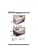
GENERAL VIEW Matrix-1000™ 1 4 6 5 7 3 2 Figure A 1 2 3 4 Reading Window Auxiliary Interface Main/Auxiliary Interface Main Tx LED 5 6 Good Read LED 7 Power On LED External Trigger LED vii
GUIDE TO INSTALLATION The following can be used as a checklist to verify all of the steps necessary for complete installation of the Matrix-1000 compact 2D reader. 1) Read all information in the section "Safety Precautions" at the beginning of this manual. 2) Correctly mount the reader using the bracket provided (sub-pars. under 2.2). 3) Position the reader at the correct reading distance according to your model (par. 2.5).
GENERAL FEATURES 1 1.1 1 GENERAL FEATURES INTRODUCTION Matrix-1000 is an area CCD reader for industrial application using 2D, 1D, stacked and postal codes. Matrix-1000 uses imaging technology and provides complete reading system functions by integrating: lighting system, image acquisition, image processing, decoding and communication into a single compact unit. This technology intrinsically provides omni-directional reading.
Matrix-1000™ 1 1.
GENERAL FEATURES 1 Electrical connection of Power, serial interfaces and I/O signals is provided through a 25-pin connector (see Figure A, 3). In addition there is a 9-pin Auxiliary interface connector for reader configuration (see Figure A, 2). The following indicators are located on the top of the reader: PWR red LED indicates that the reader is connected to the power supply (see Figure A, 7); TRIG yellow LED indicates external trigger activity (Figure A, 6); for details refer to par 2.3.
Matrix-1000™ 1 1.3 MODEL DESCRIPTION The Matrix-1000 reader is available in different versions according to the Optical Characteristics. MATRIX - 10X1 Optics 2 = High Density (HD) 3 = Standard Density (SD) 4 = Low Density (LD) 5 = Medium Range (MR) 1.4 AVAILABLE ACCESSORIES Order no.
GENERAL FEATURES 1.5 1 APPLICATION EXAMPLES The Matrix-1000™ wide choice of fields of view and high performance of decoding libraries allow the reading of many small codes (see 96 vial application in Figure 1) as well as deformed and / or overprinted codes also when they are damaged or printed on high reflective surfaces (see Figures 2, 3, 4).
1 Matrix-1000™ Figure 4 - Barcode Printed on Curved Surface Readable by Matrix-1000™ in spite of Image Optical Distortion The Matrix-1000™ is particularly suitable for applications requiring an array of readers to cover a very large reading area (see Figure 5). Figure 5 - Ten readers connected to a Datalogic MX4000 through a multidrop network.
INSTALLATION 2 2.1 2 INSTALLATION PACKAGE CONTENTS Verify that the Matrix-1000 reader and all the parts supplied with the equipment are present and intact when opening the packaging; the list of parts includes: Matrix-1000 reader Quick Reference Guide Test chart Matrix family CD-ROM Auxiliary port connector cover Mounting kit • Mounting screws and washers (4 ea.
Matrix-1000™ 2 2.2 MECHANICAL INSTALLATION Matrix-1000 can be installed to operate in different positions. The eight screw holes (M4 x 5) on the body of the reader are for mechanical fixture (Figure 7). The diagram below gives the overall dimensions of the reader and may be used for its installation. Refer to paragraph 2.5 for correct positioning. 57 [2.24] = mm [inch] M4 x 5 n°4 57 [2.24] 121 [4.76] 28.1 [1.11] = 73 [2.87] 57 [2.24] 18.1 [0.71] 57 [2.24] 4 [0.
INSTALLATION 2 73 [2.87] 95 [3.74] .2 Ø4 7] .1 [Ø0 37 [1.46] 15 [0.59] 47.5 [1.87] 2 [0.08] 47.5 [1.87] 95 [3.74] 2 8. ] Ø .32 0 [Ø 4.2 [0.
Matrix-1000™ 2 2.2.
INSTALLATION 2.3 2 ELECTRICAL CONNECTIONS The Matrix-1000 reader is equipped with a 25-pin male D-Sub connector for connection to the power supply and input/output signals.
Matrix-1000™ 2 There is also a separate 9-pin female D-sub connector for the Auxiliary port connection with the following pinout: 1 5 9 6 Figure 11 - 9-pin female D-Sub Connector 9-pin female D-sub connector pinout Pin Name 2 3 5 1,4,6,7,8,9 TXAUX RXAUX GND N.C. CAUTION Function Transmitted data of RS232 Auxiliary Interface Received data of RS232 Auxiliary Interface Reference GND of RS232 Auxiliary Interface Not connected Do not connect GND and SGND to different (external) ground references.
INSTALLATION 2 C-BOX pinout for Matrix-1000™ The table below gives the pinout of the C-BOX 100 terminal block connectors.
Matrix-1000™ 2 2.3.1 Power Supply Power is supplied to the reader through the pins provided on the 25-pin connector (see Figure 12): USER INTERFACE MATRIX VS GND SHIELD 9/13 23/25 V+ (10 - 30 Vdc) V- (Ground) 1 Figure 12 - Power Supply Connection The allowed supply voltage range is 10 to 30 Vdc.
INSTALLATION 2.3.2 2 RS485 Half-Duplex Main Interface The RS485 half-duplex (3 wires + shield) interface is available for polled communication protocols. It can be used for multidrop connections with a Datalogic Multiplexer, (see Figure 13 and par. 2.6.2).
Matrix-1000™ 2 The figure below shows a multidrop configuration with Matrix-1000™ readers connected to a Multiplexer. max. 2 m. 120 Ohm 1 MATRIX 2 #x (up to 31) 4 7 1 MATRIX 2 #1 4 7 max. 1200 m.
INSTALLATION 2.3.3 2 Auxiliary RS232 Interface The RS232 auxiliary interface is available for Point-to-Point connections. When it is connected to the host computer it allows both transmission of code data and reader configuration by VisiSet™. Its communication parameters (baud rate, data bits, etc.) can be defined by the user. For more details refer to the "Communication" folder in the VisiSet™ Help On Line.
2 Matrix-1000™ When the auxiliary interface is permanently connected as part of the system cabling, it is recommended to use the 25-pin connector and connect the cable shield as shown in Figure 15. Avoid simultaneous connection to 25-pin and 9-pin signals of the auxiliary RS232 interface.
INSTALLATION 2.3.4 2 Input An opto-coupled and polarity insensitive input is available on the 25-pin connector. The pinout is the following: Pin Name Function 18 EXT_TRIG A External trigger (polarity insensitive) 19 EXT_TRIG B External trigger (polarity insensitive) When current flows through the EXT_TRIG input, the yellow LED (Figure A, 6) is on. The External Trigger can be used in One Shot Mode or in Phase Mode.
Matrix-1000™ 2 MATRIX USER INTERFACE VS 9 + V OUT A VCC ~ - + ~ B GND GND 25 Figure 18 - Input PNP Command Using Matrix-1000 Power MATRIX Vext USER INTERFACE 30 Vdc Max. VS VCC A + V ~ - + ~ OUT B GND Figure 19 - Input NPN Command Using External Power MATRIX USER INTERFACE VS 9 A VCC + V ~ - + ~ B GND OUT GND 25 Figure 20 - Input NPN Command Using Matrix-1000 Power The electrical features of the input are: INPUT Open Closed 20 | V AB | Min. 0V 4.5 V | V AB | Max.
INSTALLATION 2 An anti-disturbance filter (debouncing) is implemented on the input, and is software programmable. The input active state can be defined by the user as well. Refer to the digital I/O folder in the VisiSet™ Help On Line for further details. 2.3.5 Outputs One optocoupled general purpose output is available on the 25-pin connector.
Matrix-1000™ 2 2.4 USER INTERFACE RS232 PC-side connections 1 5 1 6 14 9 25 25-pin male connector 9-pin male connector Pin 2 3 5 7 8 13 Name RX TX GND RTS CTS Pin 3 2 7 4 5 Name RX TX GND RTS CTS How To Build A Simple Interface Test Cable: The following wiring diagrams show a simple test cable including power, external (push-button) trigger and PC RS232 COM port connections.
INSTALLATION 2.5 2 POSITIONING Position the reader so that the distance from the reading window to the code surface is that indicated in the figure below for your model. SD HD FOV 25 x 19 mm (0.19 x 0.75 in) focus distance 115 mm (4.52 in) focus distance 155 mm (6.10 in) FOV 34 x 26 mm (1.34 x 1.02 in) code surface code surface MR LD FOV 54 x 40 mm (2.13 x 1.57 in) FOV 95 x 70 mm (3.74 x 2.75 in) focus distance 210 mm (8.26 in) focus distance 110 mm (4.
Matrix-1000™ 2 Matrix-1000 is able to decode code labels at a variety of angles, however significant angular distortion may degrade reading performance. When mounting Matrix-1000, take into consideration these ideal label position angles: Pitch 10° to 20° and Tilt 0°. Note: Since Matrix-1000 is omni-directional on the code plane, e Pitch and Skew angles have the same significance with respect to the code plane. To simplify therefore, we will use Pitch to describe both these angles.
INSTALLATION 2.6 2 TYPICAL LAYOUTS The following typical layouts refer to system hardware configurations. However, they also require the correct setup of the software configuration parameters. Dotted lines in the figures refer to optional hardware configurations within the particular layout. 2.6.1 Point-to-Point In this layout the data is transmitted to the Host on the Matrix-1000 aux serial interface. Parameter configuration can always be accomplished using the Matrix-1000 auxiliary interface.
Matrix-1000™ 2 2.6.2 Multiplexer Each reader is connected to a MX4000 through a multidrop network. Before proceeding with the connection it is necessary to select the MUX32 communication protocol and the multidrop address for each reader.
SOFTWARE CONFIGURATION 3 3 SOFTWARE CONFIGURATION Software configuration of your Matrix-1000 reader can be accomplished by VisiSet™ through the Matrix-1000 auxiliary serial interface. 3.1 VISISET™ SYSTEM REQUIREMENTS To install and run VisiSet™ you should have a Laptop or PC that meets or exceeds the following: • Pentium processor • Win 95/98/2000, NT 4.
Matrix-1000™ 3 3.3 STARTUP After completing the mechanical and electrical connections to Matrix-1000, you can begin software configuration as follows: 1. Power on the Matrix-1000 reader. Wait for the reader startup. The system bootstrap requires a few seconds to be completed. The reader automatically enters Run Mode. 2. Run the VisiSet™ program. 3. Press Connect on the VisiSet™ menu bar. The PC will automatically connect to the Matrix-1000 reader.
SOFTWARE CONFIGURATION 3.3.
Matrix-1000™ 3 Figure 30 - Options - Environment Figure 31 - Options - Communication 30
SOFTWARE CONFIGURATION 3.4 3 CONFIGURATION Once connected to Matrix-1000 as described in par. 3.3, you can modify the configuration parameters as follows: 1. Press the Calibration Tool button from the Main Menu. Matrix-1000™ will download its permanent memory configuration parameters with the default values (if it is the first time) to VisiSet™. The Calibration Tool window will be displayed together with the Parameter Setup window working in Interactive Mode (see par. 3.4.1 and par. 3.4.2). 2.
Matrix-1000™ 3 3.4.1 Edit Reader Parameters The Parameter Setup window displays the configuration parameters grouped in a series of folders. Each parameter can be modified by selecting a different item from the prescribed list in the box, or by typing new values directly into the parameter box. By right clicking the mouse when positioned over the name of a specific Parameter or Group, a pop-up menu appears allowing you to directly manage that particular parameter or group.
SOFTWARE CONFIGURATION 3 Parameters to verify/modify: Operating mode Sets the parameters which customize the reader operating mode starting from three main modes: One-shot: acquires a single image based on the selected value for the Acquisition Trigger and Delayed Triggers. Continuous: continuously acquires images with a rate up to 30 frames per second depending on the decoding time.
3 Matrix-1000™ When all the configuration parameters are set correctly, save them to the Matrix1000 reader by pressing the Send button. See Figure 32. For successive configuration of other readers or for backup/archive copies, it is possible to save the configuration onto your PC by selecting the Save pars to file option from the File menu. Load pars from file (available in the File menu) allows you to configure a reader from a previously saved configuration file.
SOFTWARE CONFIGURATION 3.4.2 3 Calibration VisiSet™ provides a Calibration Tool to maximize the reading performance by tuning the acquisition parameters and the time of the delayed triggers. By selecting the Calibration Tool from the VisiSet™ Main Menu (F), the following window appears together with the Parameter Setup window: Figure 33 - Calibration OK This tool provides a "real-time" image display while Matrix-1000™ is reading.
Matrix-1000™ 3 The following examples show some of the typical conditions occurring during the installation: Figure 34 - Example Under Exposure: Too Dark Under-exposure: To correct this result it is recommended to change the following parameters in their order of appearance: 1. 2. increase the Exposure Time (x 10 µs) increase the Gain In general, a longer exposure time corresponds to a lighter image but is susceptible to blurring due to code movement.
SOFTWARE CONFIGURATION 3 Figure 35 - Example Over Exposure: Too Light Over-exposure: To correct this result it is recommended to change the following parameters in their order of appearance: 1. 2.
Matrix-1000™ 3 Figure 36 - Example out of FOV Moving code out of the Field of View: To correct this result and have the code completely visible in the F.O.V.
SOFTWARE CONFIGURATION 3.5 3 IMAGE CAPTURE AND DECODING By using the Capture image and Decode last image functions from the VisiSet™ Main menu, you can get information about the image decodable codes in terms of Symbology, encoded Data, Position and Orientation, Decode Time and AIM Quality Indicators.
Matrix-1000™ 3 3.6 STATISTICS Statistics on the reading performance can be viewed by enabling the Statistics parameter and selecting the View stats item in the File menu. One of three different windows appears depending on the operating mode. Refer to the VisiSet™ Help On Line for more details.
MAINTENANCE 4 4.1 4 MAINTENANCE CLEANING Clean the reading window (see Figure A, 1) periodically for continued correct operation of the reader. Dust, dirt, etc. on the window may alter the reading performance. Repeat the operation frequently in particularly dirty environments. Use soft material and alcohol to clean the window and avoid any abrasive substances.
Matrix-1000™ 5 4 5 5.1 TROUBLESHOOTING GENERAL GUIDELINES • When wiring the device, pay careful attention to the pin number of the signals and whether you are referring to the 25-pin connector or to the C-BOX 100 spring clamp connectors. • If you need information about a certain reader parameter you can refer to the VisiSet program help files.
TROUBLESHOOTING 5 TROUBLESHOOTING GUIDE Problem Suggestion One Shot or Phase Mode: no image is displayed in Visiset™ Calibration Tool window while your trigger source is working. • • • • One Shot or Phase Mode using the External Trigger input: the ”TRIG” LED is not blinking while the External Trigger is switching. • • • • • • • One Shot mode using the External Trigger input: the ”TRIG" LED is correctly blinking but no image is displayed in VisiSet™ Calibration Tool window.
Matrix-1000™ 5 4 TROUBLESHOOTING GUIDE Problem Suggestion One Shot or Phase Mode using serial trigger source: no image is displayed in Visiset™ Calibration Tool window while your trigger source is transmitted on the reader serial port. • • • • Phase Mode: no result is transmitted by the reader at the end of the phase collection. • • In the Operating Mode folder check the settings for Phase-ON, Acquisition Trigger and Phase-OFF parameters.
TROUBLESHOOTING 5 TROUBLESHOOTING GUIDE Problem Suggestion How do I obtain my reader Serial Number? • • • How do I obtain my reader Order Number? • • The reader Serial Number consists of 9 characters: one letter, 2 numbers, another letter followed by 5 numbers. The reader Serial Number is printed on a label that is affixed on the bottom case near the reading window. The Serial Number can also be obtained by selecting Tools/Get reader serial number from the command menu in VisiSet.
Matrix-1000™ 6 6 TECHNICAL FEATURES ELECTRICAL FEATURES Power Supply voltage Power consumption Communication Interfaces Main Serial Interface RS485 half-duplex Auxiliary Serial Interface RS232 10 to 30 Vdc 4 W max.; 2.5 W typical 2400 to 115200 bit /s 2400 to 115200 bit /s Input External Trigger Max. voltage Max. input current Opto-coupled and polarity insensitive 30 Vdc 10 mA Output VOut (ILoad = 0 mA) VOut (ILoad = 10 mA) PD = VOut × ILoad 30 Vdc Max. 1.8 Vdc Max. 170 mW Max.
TECHNICAL FEATURES 6 SOFTWARE FEATURES READABLE CODE SYMBOLOGIES 1-D and stacked • • • PDF417 Standard Code 128 (EAN 128) Code 39 (Standard and Full ASCII) • Interleaved 2 of 5 • • • Codabar Code 93 EAN-8/13 - UPC-A/E (including Addon 2 and Addon 5 2D • Data Matrix ECC 200 POSTAL • Australia Post • Royal Mail 4 State Customer • Kix Code • Japan Post OPERATING MODE • • PLANET POSTNET, POSTNET (+BB) • POSTNET + PLANET, POSTNET (+BB) + PLANET CONFIGURATION MODE By means of VisiSet™ configuratio
Matrix-1000™ 6 READING FEATURES Frame rate up to 30 frames / sec Pitch 10° - 35° Readable codes per frame up to 100 Tilt 0° - 360° Focus Distance mm (in) 1021 HD 115 (4.52) 25 × 19 (0.98 × 0.75) 653 Typ. Linear and Stacked Code Resolution mm (mils) 0.10 (4) 1031 SD 155 (6.10) 34 × 26 (1.34 × 1.02) 478 0.15 (6) 0.25 (10) 135 (5.31) 180 (7.08) 1041 LD 110 (4.33) 300 0.20 (8) 0.38 (15) 90 (3.45) 140 (5.51) 1051 MR 210 (8.26) 170 0.30 (12) 0.60 (24) 150 (5.90) 250 (9.
GLOSSARY Barcode A pattern of variable-width bars and spaces which represents numeric or alphanumeric data in machine-readable form. The general format of a barcode symbol consists of a leading margin, start character, data or message character, check character (if any), stop character, and trailing margin. Within this framework, each recognizable symbology uses its own unique format. BIOS Basic Input Output System.
Light Emitting Diode (LED) A low power electronic light source commonly used as an indicator light. It uses less power than an incandescent light bulb but more than a Liquid Crystal Display (LCD). RAM Random Access Memory. Data in RAM can be accessed in random order, and quickly written and read. IP Address The terminal’s network address. Networks use IP addresses to determine where to send data that is being transmitted over a network.
INDEX A Accessories; 4 Application Examples; 5 C C-BOX pinout for Matrix-1000™; 13 Configuration; 31 Calibration; 35 Edit Reader Parameters; 32 E Electrical Connections; 11 Auxiliary RS232 Interface; 17 Inputs; 19 Outputs; 21 Power Supply; 14 RS485 Half-Duplex Interface; 15 G General View; vii Glossary; 49 Guide to Installation; viii L Layouts; 25 Multiplexer; 26 Point-to-Point; 25 M Maintenance; 41 Cleaning; 41 Mechanical Installation; 8 Model description; 4 Mounting Matrix-1000™; 10 P Package Contents;
DATALOGIC S.p.A.