
Barcode Reader User Manual

INSTALLATION
11
2
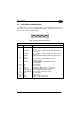
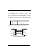
2.3 ELECTRICAL CONNECTIONS
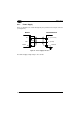
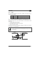
The Matrix-1000 reader is equipped with a 25-pin male D-Sub connector for
connection to the power supply and input/output signals. The details of the connector
pins are indicated in the following table:
13
2514
1
Figure 10 - 25-pin male D-Sub Connector
25-pin male D-sub connector pinout
Pin Name Function
1 SHIELD Cable shield internally connected by capacitor to the
chassis
2 RTX485+ Rx or Tx data of RS485 Half Duplex Main Interface -
positive pin
4 RTX485- Rx or Tx data of RS485 Half Duplex Main Interface -
negative pin
7 SGND Reference GND of RS485 Half Duplex Main Interface
3,5 NC
20 RXAUX Received data of RS232 Auxiliary Interface
(referred to GND)
21 TXAUX Transmitted data of RS232 Auxiliary Interface
(referred to GND)
8, 22 NC Not connected
11, 12 NC Not connected
16 OUT 3 + Configurable digital output 3 - positive pin
17 OUT 3 - Configurable digital output 3 - negative pin
18 EXT_TRIG A External trigger (polarity insensitive)
19 EXT_TRIG B External trigger (polarity insensitive)
6, 10 NC Not connected
14, 15, 24 NC Not connected
9,13 VS Supply voltage - positive pin
23, 25 GND Supply voltage - negative pin