Datalogic Memor™ www.mobile.datalogic.com World wide Sales Network available from: www.mobile.datalogic.com/contacts Datalogic Mobile S.r.l. Via S. Vitalino, 13 40012 Lippo di Calderara di Reno Bologna - Italy Telephone: (+39) 051-3147011 Fax: (+39) 051-3147561 User’s Manual ©2008 Datalogic Mobile S.r.l.
Datalogic Mobile S.r.l. Via S. Vitalino 13 40012 - Lippo di Calderara di Reno Bologna - Italy Datalogic Memor™ - User's Manual Software Version: 3.00 Ed.: 07/2008 ALL RIGHTS RESERVED Datalogic is a registered trademark of Datalogic S.p.A. in many countries and the Datalogic logo is a trademark of Datalogic S.p.A.. All other brand and product names mentioned herein are for identification purposes only and may be trademarks or registered trademarks of their respective owners.
CONTENTS DATALOGIC END USER LICENSE AGREEMENT ............................v REFERENCES...................................................................................vii Conventions ....................................................................................... vii Reference Documentation ................................................................. vii Services and Support ......................................................................... vii SAFETY REGULATIONS .......................
3.5.2 3.6 3.6.1 3.6.2 3.6.3 3.6.4 3.6.5 3.6.6 3.7 3.7.1 3.7.2 3.7.3 3.8 3.9 Capture.............................................................................................. 28 Control Panel .................................................................................... 29 Buttons .............................................................................................. 29 Registry ............................................................................................. 30 Files Admin ....
DATALOGIC END USER LICENSE AGREEMENT BY DOWNLOADING OR INSTALLING THE SOFTWARE, OR BY USING DATALOGIC EQUIPMENT THAT INCLUDES THIS SOFTWARE, YOU ARE CONSENTING TO BE BOUND BY THIS AGREEMENT. IF YOU DO NOT AGREE TO ALL OF THE TERMS OF THIS AGREEMENT, THEN DO NOT DOWNLOAD, INSTALL, USE THE SOFTWARE NOR DATALOGIC EQUIPMENT.
and/or copyrighted material of Datalogic. Customer shall not disclose, provide, or otherwise make available such trade secrets or copyrighted material in any form to any third party without the prior written consent of Datalogic. Customer shall implement reasonable security measures to protect such trade secrets and copyrighted material. Software and documentation shall remain solely property of Datalogic. 6. Limited Warranty.
REFERENCES CONVENTIONS This manual uses the following conventions: “User” refers to anyone using a Datalogic Memor™ mobile computer. “Mobile computer” and "Datalogic Memor™" refer to Datalogic Memor™ mobile computer. “You” refers to the System Administrator or Technical Support person using this manual to install, configure, operate, maintain or troubleshoot a Datalogic Memor™ mobile computer. “Single Cradle” refers to both Datalogic Memor™ Single Cradle and Datalogic Memor™ Single Ethernet Cradle.
SAFETY REGULATIONS NOTE Read this manual carefully before performing any type of connection to the Datalogic Memor™ mobile computer. The user is responsible for any damages caused by incorrect use of the equipment or by inobservance of the indication supplied in this manual. GENERAL SAFETY RULES − Use only the components supplied by the manufacturer for the specific Datalogic Memor™ being used.
LASER SAFETY The laser light is visible to the human eye and is emitted from the window indicated in the figure. This information applies to both laser models and the Datalogic Memor™ Imager Aiming System. Laser output window AVOID EXPOSURE LASER LIGHT IS EMITTED FROM THIS APERTURE This product complies with 21 CFR Subchapter J CAUTION-CLASS 2 LASER LIGHT WHEN OPEN - DO NOT STARE INTO BEAM LASER LIGHT - DO NOT STARE INTO BEAM CLASS 2 LASER PRODUCT MAX. OUTPUT RADIATION 1.
I D LUCE LASER NON FISSARE IL FASCIO APPARECCHIO LASER DI CLASSE 2 MINIMA POTENZA DI USCITA: LUNGHEZZA D'ONDA EMESSA: CONFORME A EN 60825-1 (2001) LASERSTRAHLUNG NICHT IN DER STRAHL BLINKEN PRODUKT DER LASERKLASSE 2 MAXIMALE AUSGANGLEISTUNG: WELLENLÄNGE: ENTSPR.
ENGLISH The following information is provided to comply with the rules imposed by international authorities and refers to the correct use of your mobile computer. STANDARD LASER SAFETY REGULATIONS This product conforms to the applicable requirements of both CDRH 21 CFR 1040 and EN 60825-1 at the date of manufacture. For installation, use and maintenance, it is not necessary to open the device.
NORM FÜR DIE LASERSICHERHEIT Dies Produkt entspricht am Tag der Herstellung den gültigen EN 60825-1 und CDRH 21 CFR 1040 Normen für die Lasersicherheit. Es ist nicht notwendig, das Gerät wegen Betrieb oder Installations-, und Wartungs-Arbeiten zu öffnen. Jegliche Änderungen am Gerät sowie Vorgehensweisen, die nicht in dieser Betriebsanleitung beschrieben werden, können ein gefährliches Laserlicht verursachen. ACHTUNG Der Produkt benutzt eine Laserdiode.
La utilización de procedimientos o regulaciones diferentes de aquellas describidas en la documentación puede causar una exposición peligrosa a la luz láser visible. ATENCIÓN El aparato utiliza un diodo láser a baja potencia. No son notorios daños a los ojos humanos a consecuencia de una exposición de corta duración. Eviten de mirar fijo el rayo láser así como evitarían cualquiera otra fuente de luminosidad intensa, por ejemplo el sol.
RADIO COMPLIANCE In radio systems configured with mobile computers and access points, the frequencies to be used must be allowed by the spectrum authorities of the specific country in which the installation takes place. Be absolutely sure that the system frequencies are correctly set to be compliant with the spectrum requirements of the country. The following shows the correspondence between the Datalogic Memor™ models and the Radio components: Datalogic Memor™ 6XX-XXX-XXX 802.
FCC COMPLIANCE Modifications or changes to this equipment without the expressed written approval of Datalogic could void the authority to use the equipment. This equipment has been tested and found to comply with the limits for a Class B digital device, pursuant to Part 15 of the FCC Rules. These limits are designed to provide reasonable protection against harmful interference in a residential installation.
WEEE COMPLIANCE Informazione degli utenti ai sensi della Direttiva Europea 2002/96/EC L’apparecchiatura che riporta il simbolo del bidone barrato deve essere smaltita, alla fine della sua vita utile, separatamente dai rifiuti urbani.
éviter les retombées négatives pour l'environnement et la santé dérivant d'une élimination incorrecte récupérer les matériaux dans le but d'une économie importante en termes d'énergie et de ressources Pour obtenir des informations complémentaires concernant l'élimination, veuillez contacter le fournisseur auprès duquel vous avez acheté le produit ou consulter la section consacrée au site Web www.mobile.datalogic.com.
CHINA ROHS POLLUTION CONTROL LOGOS Part name Upper Case Lower Case Touch Panel PCB Board Laser Engine BT Module (Note 1) WiFi Module (Note 2) WiFi Module (Note 3) Pb Toxic or Hazardous Substances and Elements Hg Cd Cr6+ PBB PBDE O O O O O O O O O O O O O O O O O O O O O O O O X O O O O O O O O O O O O O O O O O O O O O O O O: Indicates that this is a toxic or hazardous substance contained in all of the homogenous materials for this part is below the limit
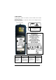
GENERAL VIEW G B K C A H F I D J E A) B) C) D) E) F) Transflective 64K Color Display Good Read or User Programmable LED Charging Status LED Scan Key Keyboard Radio Status LED G) Strap with Stylus Holder H) Laser Safety Label I) Product Label (under battery) J) Battery Pack K) ON/OFF Power Key M N 0 L L) M) Data Capture/Laser Output Window * DC Charger Connector N) Communication/Charger Connector (through cradle) O) Mini USB Communication/Charger Connector (through cable) • Remove protective
xx
INTRODUCTION 1 1.1 1 INTRODUCTION DATALOGIC MEMOR™ DESCRIPTION The Datalogic Memor™ is a pocket-sized Windows powered mobile computer. This extremely compact, lightweight, and versatile device, combines fully integrated automatic data capture (1D bar code) and wireless communication capabilities (Bluetooth® or 802.11 b/g), supporting nearly any application.
DATALOGIC MEMOR™ 1 1.3 PACKAGE CONTENTS The Datalogic Memor™ package contains: − 1 Datalogic Memor™ mobile computer − 1 AC/DC power supply − 1 EU plug adapter − 1 AUS.
INTRODUCTION 1.4 1 INSERTING AN SD CARD Datalogic Memor™ provides the possibility to add an SD memory storage card. To access the SD card slot and to insert the card, proceed as follows: 1. Extract the SD card slot cover from side of the mobile computer. Then carefully pull it out till unlocking its base as shown in the picture below: 2. Insert the card with the written part upward and push it in, aided by the back of the stylus, until it clicks into place.
DATALOGIC MEMOR™ 1 1.5 ACCESSORIES Cradles 94A151111 Datalogic Memor™ Single Cradle 94A151116 Datalogic Memor™ Single Ethernet Cradle Batteries 94ACC1326 Datalogic Memor™ Standard Battery Pack (Li-Pol or Li-Ion battery pack 1000 mAh@3.7 V) 94ACC1325 Datalogic Memor™ Large Capacity Battery Pack (Li-Pol or LiIon battery pack 2000 mAh@3.7 V) + cover 94ACC1327 Adapter for 3 AAA Alkaline batteries + cover Power Supply 94ACC1324 PG5-30P35 AC/DC Power Supply EU/USA Plug 94ACC1334 PG5-30P35 AUS.
CONNECTIONS 2 2 CONNECTIONS 2.1 USB CONNECTION You can use any standard mini USB cable to directly connect the Datalogic Memor™ to a host computer to transfer data through the USB interface. A C B Key: A) Host Computer B) Standard Mini USB cable C) Datalogic Memor™ The Single Cradle can be connected to the Host by any standard mini USB cable to transfer data through the USB interface.
DATALOGIC MEMOR™ 2 1 2.2 RS232 CONNECTION You can use a cable to directly connect the Datalogic Memor™ to a host computer to transfer data through the RS232 interface. A C B Key: A) Host Computer B) 94A051022 WIN-NET (HRS ST40X-18S-CV) C) Datalogic Memor™ The Single Cradle can be connected to the Host by any standard 9-pin serial null-modem cable for RS232 communications. Once the Host has been turned on, insert the Datalogic Memor™ mobile computer into the cradle.
CONNECTIONS 2.3 2 ETHERNET CONNECTION The Datalogic Memor™ Single Ethernet Cradle provides an Ethernet connection. Connect the Ethernet cradle (Ethernet port) to an Ethernet hub or switch. Connect the power jack to a power supply*. A D* B * C A) Datalogic Memor™ Single C) Ethernet Cradle UTP CAT 5E cable (recommended use) B) Ethernet hub *Power supply D) Recommended power supply: 94ACC1324 PG5-30P35 AC/DC POWER SUPPLY EU/USA PLUG.
DATALOGIC MEMOR™ 2 1 2.4 WLAN CONNECTION Datalogic Memor™ Wi-Fi 802.11 b/g radio models can communicate with the host using the on-board radio frequency component and an Access Point connected to the host computer. For models using the WiFi8 radio (8xx-xxx-xxx models), you can find information about the applet for radio configuration: http://www.summitdatacom.com/SCU.htm.
CONNECTIONS 2 Wi-Fi module is on by default, in order to avoid wasting energy, you can switch it off using the Wireless Communications applet. NOTE NOTE NOTE Suspending the terminal powers off the 802.11b/g radio and drops the radio connection. When the terminal resumes, depending on the radio power mode and security protocol selected, it may take up to 30 seconds for the 802.11b/g radio driver to re-associate the radio to the network.
DATALOGIC MEMOR™ 2 1 2.5 WPAN CONNECTIONS Bluetooth® Datalogic Memor™ mobile computer models can communicate with a Bluetooth® device, such as a printer, within a range of 10 m, using the onboard Bluetooth® module. B A Key: A) Datalogic Memor™ B) Bluetooth® printer NOTE NOTE In order to avoid wasting energy, the Bluetooth® module is off by default. If you need to have Bluetooth® working, the module must be powered on using the Wireless Communications applet (see par. 3.6.
CONNECTIONS 2.
DATALOGIC MEMOR™ 3 1 3 USE AND FUNCTIONING The use of the Datalogic Memor™ depends on the application software loaded. However there are several parameters that can be set and utilities that can be used to perform some basic functions such as data capture, communications, file management, etc. 3.1 STARTUP The Datalogic Memor™ turns on when the battery pack or the external supply is inserted. After the battery pack is installed, use the [ON/OFF] key to turn the mobile computer on and off.
USE AND FUNCTIONING 3 The mobile computer can also be awakened or turned off by the application program.
DATALOGIC MEMOR™ 3 1 3.1.1 Using the Stylus The stylus selects items and enters information. The stylus functions like a mouse. Double Tap: Touch the screen twice with the stylus to open items and select options. Drag: Hold the stylus on the screen and drag across the screen to select text and images. Drag in a list to select multiple items. Tap and hold the stylus on an item to see a list of actions Tap-and-hold: available for that item.
USE AND FUNCTIONING 3.1.2 3 Using the Joystick The joystick selects items and enters information. The joystick can work like the directional arrow keys of a PC keyboard or can function like a mouse and control the mouse pointer. It is possible to switch between the two functioning modes by pressing blue modifier + BKSP keys in sequence.
DATALOGIC MEMOR™ 3 1 3.2 DATA CAPTURE To capture data first of all select the barcode icon on the bottom-right side of the display and tap the 'Capture' menu item then proceed with the following directions. To configure and enable data capture parameters refer to par. 3.5. 3.2.1 Laser Data Capture To scan barcodes, point the Datalogic Memor™ laser model onto the code from a distance within the reading range while pressing the SCAN key.
USE AND FUNCTIONING 3.3 3 DESCRIPTION OF THE KEYS The Datalogic Memor™ provides a 20-key alphanumeric keyboard + ON/OFF key + joystick. The following image shows this keyboard.
DATALOGIC MEMOR™ 3 1 Main Keys Function KEY FUNCTION It starts barcode data capture. The joystick lets you move forwards, backwards, upwards or downwards, scroll through a Menu list, browse among folder files or select functions if pressed down. It can work in two functioning modes: Arrow Keys Mode and Mouse Mode. It’s possible to switch between them by pressing blue modifier + BKSP keys in sequence (see par. 3.1.
USE AND FUNCTIONING 3.3.1 3 Resetting the Memor™ There are several reset methods for the Memor™. A warm boot terminates an unresponsive application and clears the working RAM, but preserves both the file system and the registry. A cold boot forces all applications to close and clears working RAM and files not resident on the persistent flash memory. Registry is restored from persistent memory if available or returned to factory default.
DATALOGIC MEMOR™ 3 1 Warm Boot Cold Boot REGISTRY Preserved Restored from flash (if available) Flash Disk (Backup Folder) RAM File System Preserved Preserved Preserved Reinitialized (factory default) Clean Boot Factory default Clean disk Factory default Before performing a reset, it is recommended to: CAUTION 20 - execute a system backup to keep your more important files and applications persistent. See par. 3.
USE AND FUNCTIONING 3.4 3.4.1 3 STATUS INDICATORS LED Status The Datalogic Memor™ provides three different LEDs signaling the mobile computer status. LED STATUS Good Read and General Purpose (left side) Green It is constant for a configurable time to signal that a successful read has occurred. Green/Red It is also available to the application program. Green constant It is constant once the charging process has been completed. Red constant It is constant while charging.
DATALOGIC MEMOR™ 3 1 ICONS DESCRIPTION Time and Battery Icons It displays the time. They are representative of five different icons indicating the battery level. The icon is partially green when the power left is >20% and partially red colored when the power left is <20%. It indicates that the battery is charging. Keyboard Status Icons It indicates that the blue FUNC key has been pressed and is going to affect the next key press.
USE AND FUNCTIONING 3.5 3 DATA CAPTURE CONFIGURATION From the Taskbar, tap the "Decoding" icon to open a drop–down menu. Decoding can also be accessed from the Control Panel. By selecting the Info item from this drop-down menu you can access information about the Scanner and the Software; the Configure item opens the configuration applet (Data Capture Configuration Window), while Capture accesses the data capture applet (Data Capture Window), which enables code reading.
3 1 DATALOGIC MEMOR™ Data Capture Configuration Window The screen format shows two columns where the left column indicates branches or parameters. Branches have three dots in the right column (...). You can navigate through the tree structure using the stylus or keyboard arrows directly on the item field or from the menu. Parameters have their corresponding current values in the right column. You can edit parameter values using the stylus or keyboard arrows directly on the item field or from the menu.
USE AND FUNCTIONING 3 Alternatively using the stylus, you can tap once directly on the value on the right column; continue tapping until the desired value is reached. To activate a new configuration select the File ->Save Menu to send the new configuration to the barcode decoding software and save the new configuration. This will save the configuration to non-volatile memory preventing loss at the next system reset.
3 1 DATALOGIC MEMOR™ Reader Parameters The barcode reading parameters and values are dependent upon the type of scanner module mounted in your mobile computer. For a detailed list of parameters and of their configuration procedures, please refer to the SDK Help file on the CD. Scan Parameters The Scan Parameters are common to all scanner modules and allow control of the scanning device.
USE AND FUNCTIONING 3 Default Settings The following tables contain the default values for the major barcode setup parameters, according to the type of scan engine mounted on the mobile computer. For a complete list of parameters and of their configuration procedures, please refer to the SDK Help file on the CD.
DATALOGIC MEMOR™ 3 1 3.5.2 Capture The Data Capture applet (Capture) enables code reading. Data Capture Window Data Capture can also be enabled through the Configuration applet by selecting File ->Scanner from the main menu, or by enabling the parameter Scan Always On in the Scan Parameters branch.
USE AND FUNCTIONING 3.6 3 CONTROL PANEL From the Desktop, double tap on the "My Device" icon and then double tap on the "Control Panel" icon to open the control panel main window. The Control Panel can also be launched from Start ->Settings ->Control Panel. APPLET programs are displayed as icons; one icon corresponds to each APPLET. Control Panel 3.6.1 Buttons The BUTTONS Applet allows assigning desired applications to be launched by one of the function keys (F1...F4).
DATALOGIC MEMOR™ 3 1 3.6.2 Registry The REGISTRY ADMIN applet provides management of Windows CE 5.0 registry. Select the REGISTRY ADMIN applet by double tapping the Registry Admin icon. The Registry Administration Main window appears. Two functions are available: - Save Registry allows permanently saving the Windows configuration (example: custom configuration of screen desktop background color, or network adapter configuration) to non-volatile memory (SAVE button).
USE AND FUNCTIONING 3.6.3 3 Files Admin The FILES ADMIN applet enables control of the permanence of files in the System Folder. Two functions are available on the Files Admin Main window by means of two buttons: Files Admin Main Window Save Session: with this button all files will be permanently saved in the \Windows directory in non-volatile memory.
DATALOGIC MEMOR™ 3 1 Safe Setup First Mask Then select \Windows or a relevant sub-directory in the path box. Then, Safe Setup will recognize the new files and directories present in the \Windows directory, and will copy them to the \Backup\Windows directory. At the next cold boot, these files will be restored (see par. 3.8). - Simply skip the first mask either by closing it or by pressing the ESC key.
USE AND FUNCTIONING 3.6.4 3 Wireless Communications The WIRELESS COMMUNICATIONS applet provides management of the 802.11 b/g radio and of the Bluetooth® module. Select the WIRELESS COMMUNICATIONS applet by double tapping the Wireless Communications icon.
DATALOGIC MEMOR™ 3 1 3.6.5 Ethernet Settings Datalogic Memor™ can be connected to an Ethernet network by inserting it into the Datalogic Memor™ Single Ethernet Cradle. NOTE Ethernet communication requires Datalogic Memor™ SW version 5.51 or later. Verify the software version by tapping on Software – Version in the Datalogic default home page. Otherwise, search for the file version.htm under the Windows folder.
USE AND FUNCTIONING 3.6.6 3 Stylus Calibration You might need to recalibrate the touch screen (i.e. when you attempt to select one item with the stylus, another item is erroneously selected). To recalibrate the touch screen, complete the following steps: 1. Select Start > Settings > Control Panel > Stylus to open the Stylus Properties dialog as shown in Figure 1. 2. Adjust Double-Tap sensitivity if needed or desired. 3. Select the Calibration tab to open the Calibration application. Figure 1 4. 5. 6.
DATALOGIC MEMOR™ 3 1 Figure 2 Startup stylus calibration When starting the terminal, a stylus calibration screen comes up if valid calibration settings are not available. This happens in the following circumstances: 1. 2. 3. 4. 36 At the first startup of the terminal. After restoring registry default settings using the applet Registry Admin and performing a warm boot. After a Clean Boot. After a Firmware Update (see par. 3.9).
USE AND FUNCTIONING 3.7 3 WINDOWS CONNECTIONS To connect the Datalogic Memor™ to another device (i.e. Host PC) from Windows, several programs are available. These programs require specific electrical connections in order to function properly. 3.7.1 Microsoft® ActiveSync® ® ® Microsoft ActiveSync gives you the possibility to connect your desktop computer to your Datalogic Memor™ and synchronize the information on them.
DATALOGIC MEMOR™ 3 1 ActiveSync® Remote NOTE 38 Microsoft® ActiveSync® Remote is no longer supported in Windows CE. For backward compatibility you can download it from the Internet. We suggest enabling the FTP Server and connecting to an FTP Client. See par. 3.7.3.
USE AND FUNCTIONING 3.7.2 3 Bluetooth® Manager Device Setup In order to enable a Bluetooth® device for communication with the Datalogic Memor™ you must perform the discovery procedure and enable the device as follows: 1. Place the Bluetooth® device within the range of the Datalogic Memor™ (10 meters). 2. From the “Control Panel” main window double tap on the “Bluetooth” applet ® to open the Bluetooth Manager Device window: 3.
3 1 4. DATALOGIC MEMOR™ Tap on the “Discovery” button to enter the related window; then, tap on the “Scan” button to run the Discovery procedure: Once the Discovery procedure has been completed, select the desired Bluetooth® device from the list. It is also possible to digit (12 hexadecimal digits) the Bluetooth® address of the desired device by tapping on the “Add” button. The “Clear” button deletes all discovered devices from the list. 5.
USE AND FUNCTIONING 6. 3 Hide the Bluetooth® Manager Device window by tapping on the icon available on each window or close it through the “Close” button available in the “Me” window (see step 3 of this procedure).
DATALOGIC MEMOR™ 3 1 3.7.3 FTP Server Setup The Datalogic Memor™ Operating System includes a sample File Transfer Protocol (FTP) server. FTP is used for copying files to and from remote computer systems over a network using TCP/IP. You can establish a connection to your Datalogic Memor™ using its FTP Server through the following interfaces: WLAN using the WiFi radio LAN through the Datalogic Memor™ Single Ethernet Cradle. Proceed as follows: 1. Create a registry file (extension .
USE AND FUNCTIONING 3.8 3 BACKUP DIRECTORY FILE MANAGEMENT All of the Windows CE 5.0 system files reside in RAM (volatile memory) except for the Backup directory, which resides in FLASH (non-volatile memory). Therefore the contents of the Backup directory are persistent even if the mobile computer is re-booted or the battery pack is changed. You can save your more important files that you don't want to lose due to mobile computer re-boot, in the Backup directory or create a sub-directory within Backup.
DATALOGIC MEMOR™ 3 1 3.9 FIRMWARE UPDATE The Datalogic Memor™ is equipped with a tool that implements a firmware update service. This tool, called Datalogic Updater (DLUpdater), is compatible with all hardware versions of the following WindowsCE 5.0 models: Datalogic Skorpio™; Datalogic Jet™; Datalogic Kyman™; Datalogic Memor™. The DLUpdater, that is automatically invoked at startup, search for a potential update file (DLUpdate.bin) in the storage card.
USE AND FUNCTIONING 3 Firmware Update Procedure 1. Download the update from the web site (see previous par.). It is a zip file containing the files: • DLUpdater.exe – that starts the update; • DLUpdate.bin – binary file containing the updated firmware; 2. Copy the files DLUpdater.exe (optional) and DLUpdate.bin on a Mini SD card. 3. Insert the Mini SD card in the terminal slot (see par. 1.4). 4. Open the folder “\Storage Card” on the terminal and run DLUpdater.exe (double tap the icon).
DATALOGIC MEMOR™ 3 1 whether to proceed with this operation. Select to format the flash disk. Select to preserve the current data stored in the backup folder. Sometimes the update process may force a flash format. In these cases the data stored in the backup folder will be irreparably lost. It is therefore recommended to run a backup of the data you want to preserve before starting a firmware update.
MAINTENANCE 4 4 MAINTENANCE Rechargeable backup batteries and battery packs are not initially charged. Therefore the initial operation to perform is to charge them. See below. NOTE CAUTION 4.1 By default, the backup battery is disconnected at the factory to avoid damage due to excessive draining. If it is not connected (through the backup battery switch) and subsequently charged together with the battery pack, all data will be lost when changing the battery pack.
4 1 DATALOGIC MEMOR™ Be careful when using sharp-edged tools to move the switch from the “disconnected” position to the "connected" position and vice versa! CAUTION 48
MAINTENANCE 4.2 4 CHARGING THE BATTERY PACK The battery pack autonomy varies according to factors, such as the frequency of barcode scanning, RF usage, etc. The battery icon on the Taskbar indicates when the battery pack is low. It is possible to recharge the battery pack by connecting the power supply directly to the Datalogic Memor™. Alternatively, it is also possible to recharge the battery pack by using a Single Cradle.
DATALOGIC MEMOR™ 4 1 4.3 REPLACING THE BATTERY PACK To correctly replace the battery pack, proceed as follows. 1. Turn off the Datalogic Memor™. 2. Use the back of the stylus to rotate the battery cover screw to the vertical position, then push the battery clips in, as indicated in the figure below. The battery pack cover is now released. 3. Remove the cover and then the battery pack.
MAINTENANCE 4 4. Install the new battery pack, first insert the bottom (contacts) side, then the upper (lock) side as indicated in the following figure: 5. For correct locking, push the battery clips outwards and rotate the screw to the horizontal position.
DATALOGIC MEMOR™ 4 1 Use only a Datalogic Mobile approved power supply. Use of an alternative power supply will void the product warranty and may cause product damage. Do not apply voltages to the batteries WARNING contacts. Risk of explosion if the battery is replaced by an incorrect type. Do not use the batteries of this terminal to power devices different from this mobile computer. Do not place the battery in or near a fire or heat as they may explode.
MAINTENANCE NOTE 4 In order to guarantee an adequate operating autonomy, when replacing the battery pack the mobile computer checks the battery energy level. If the battery is not sufficiently charged, Datalogic Memor™ does not turn on (when pressing the ON/OFF key). In this case, either substitute the battery pack with a charged one (sufficiently charged) or insert Datalogic Memor™ into a powered cradle or plug it into the direct power supply.
DATALOGIC MEMOR™ 5 1 5 5.1 TECHNICAL FEATURES TECHNICAL DATA Datalogic Memor™ Common Features Electrical Features Power DC Supply Battery Pack 5 V ± 5% 1 cell Li-Pol or Li-Ion 1000 mAh@3.7 V (nominal) Alternatively 1 cell Li-Pol or Li-Ion 2000 mAh@3.
TECHNICAL FEATURES Mechanical Features Dimensions (LxWxH) Weight (depending on model) Programming Features Operating system Laser Models Decoded barcodes 1D 5 15.2 x 5.5 x 4.0 cm / 5.9 x 2.2 x 1.6in 210 g / 7.40 oz (incl. 1000 mAH battery) 240 g / 8.46 oz (incl. 2000 mAH battery) Windows CE 5.
DATALOGIC MEMOR™ 5 1 5.
TEST CODES 6 6 TEST CODES High Density Codes 0.
DATALOGIC MEMOR™ 6 1 Medium Density Codes 0.
TEST CODES 6 Low Density Codes 0.
GLOSSARY Access Point A device that provides transparent access between Ethernet wired networks and IEEE 802.11 interoperable radio-equipped mobile units. Hand-held mobile computers, PDAs or other devices equipped with radio cards, communicate with wired networks using Access Points (AP). The mobile unit (mobile computer) may roam among the APs in the same subnet while maintaining a continuous, seamless connection to the wired network.
Host A computer that serves other mobile computers in a network, providing services such as network control, database access, special programs, supervisory programs, or programming languages. Liquid Crystal Display (LCD) A display that uses liquid crystal sealed between two glass plates. The crystals are excited by precise electrical charges, causing them to reflect light outside according to their bias. They use little electricity and react relatively quickly.
INDEX Glossary; 60 A Accessories; 4 ActiveSync® Remote; 38 B Backup Directory File Management; 43 Bluetooth® Manager Device Setup; 39 Buttons; 29 C Charging the Batteries; 49 China RoHS Pollution Control Logos; xviii Cleaning the Mobile Computer; 53 Connecting the Backup Battery; 47 Connection Cables; 11 RS232 Direct Connection; 11 Connections; 5 Control Panel; 29 Conventions; vii D Data Capture; 16 Laser Data Capture; 16 Data Capture Configuration; 23 Datalogic Memor™ Description; 1 Default Settings; 27 De
Using the Joystick; 15 Using the Stylus; 14 W Windows Connections; 37 Wireless Communications; 33 WLAN Connection; 8 WPAN Connections; 10 WEEE Compliance; xvi 63
Datalogic Mobile S.r.l. Via S.
Datalogic Memor™ www.mobile.datalogic.com World wide Sales Network available from: www.mobile.datalogic.com/contacts Datalogic Mobile S.r.l. Via S. Vitalino, 13 40012 Lippo di Calderara di Reno Bologna - Italy Telephone: (+39) 051-3147011 Fax: (+39) 051-3147561 User’s Manual 822000705 (Rev. E) ©2008 Datalogic Mobile S.r.l.