SC6000 Controller QUICK REFERENCE GUIDE
CONTENTS SC6000-1200 STANDARD MODEL ........................................................................................................................1 SC6000-1211 PROFIBUS MODEL ..........................................................................................................................4 SC6000-1215 DEVICENET MODEL ........................................................................................................................5 SC6000-1230 DUAL ETHERNET MODEL .....................
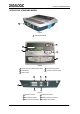
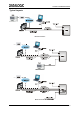
SC6000 STANDARD MODEL SC6000-1200 STANDARD MODEL 1 Figure A 1 Connector Panel 3 2 1 4 5 Figure B 1 Power ON and Communication LEDs 2 LCD Display 4 Programming Keypad 5 Connector Panel Legend 3 Status LEDs 3 2 4 1 6 5 Figure C 1 Modem Connector 4 Ethernet Connector 2 Power/Net Connector 5 Auxiliary Interface Connector 3 Main Interface Connector 6 Extended I/O Connector 1
SC6000 STANDARD MODEL Electrical Connections The SC6000 is designed to easily connect to the PWO power supply through two standard accessory cables. All system cabling is concentrated at the PWO except for some Host connections and the Auxiliary interface for SC6000 configuration using a laptop PC. The following connector pinouts are given for reference.
SC6000 STANDARD MODEL Typical Layouts Ethernet Connection Main Connection Modem Connection 3
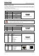
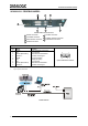
SC6000 PROFIBUS MODEL SC6000-1211 PROFIBUS MODEL 2 3 7 6 4 1 5 SC6000 Profibus Connector Panel 1 Modem Connector 5 Profibus Connector 2 Power/Net Connector 6 Auxiliary Interface Connector 3 Main Interface Connector 7 Extended I/O Connector 4 Ethernet Connector PROFIBUS CONNECTOR Pin 1 2 3 4 5 6 7 8 9 Name Shield* N.C. B-LINE (RxD/TxD-P) CNTR-P** DGND +5 V N.C. A-LINE (RxD/TxD-N) CNTR-N** * signal is optional ** signal is optional; RS485 level Function Shield, protective ground resp.
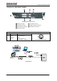
SC6000 DEVICENET MODEL SC6000-1215 DEVICENET MODEL 3 2 4 1 5 6 7 SC6000 DeviceNet Connector Panel 1 Modem Connector 5 DeviceNet Connector 2 Power/Net Connector 6 Auxiliary Interface Connector 3 Main Interface Connector 7 Extended I/O Connector 4 Ethernet Connector DEVICENET CONNECTOR Pin 2 5 1 4 3 Name V+ CAN_L SHIELD CAN_H V- Function Supply voltage – positive pin CAN bus data line – L Shield CAN bus data line – H Supply voltage – negative pin 4 3 1 2 5 5-pin male DeviceNet Connector
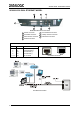
SC6000 DUAL ETHERNET MODEL SC6000-1230 DUAL ETHERNET MODEL 2 3 7 6 4 1 5 SC6000 Dual Ethernet Connector Panel 1 Modem Connector 5 Second Ethernet Connector 2 Power/Net Connector 6 Auxiliary Interface Connector 3 Main Interface Connector 7 Extended I/O Connector 4 Ethernet Connector ETHERNET CONNECTOR Pin Name Function 1 2 3 6 4, 5, 7, 8 TX + TX RX + RX N.C.
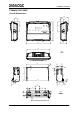
COMMON FEATURES COMMON FEATURES Overall Dimensions 39.7 [1.56] 124.4 [4.90] 99.7 [3.93] MØ8 248.7 [9.79] 124.4 [4.90] 39.7 [1.56] 80.2 [3.16] 319.5 [12.58] 298 [11.73] mm inch SC6000 Overall Dimensions N° [R 2 R 0. 1 59 5 ] 300 [11.80] 48 [1.89] 16 [0.63] N°6 8 [0.32] N°2 R10 [R0.39] 180 [7.09] 50 [1.97] 5 [0.20] 30 [1.18] 16 [0.63] 15 [0.59] M8 309 [12.17] 85 [3.35] 40 [1.57] 85 [3.35] 40 [1.57] 48 [1.89] 40 [1.57] mm inch 56 2Ø N° 2.22] [Ø [0 8 .3 3] 15 [0.59] 95 [3.
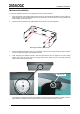
COMMON FEATURES Mechanical Installation To mount the SC6000 Controller on the reading station frame proceed as follows: 1 Mount the bracket on the reading station frame: the slots on the bracket will help obtain the best positioning. When working in environments characterized by strong vibrations, set the screws as close as possible to the bracket edges, see the figure below. 2 Tighten the ST-222 bracket to the reading station frame using the screws and washers.
COMMON FEATURES 5 Place a locking washer and then a flat washer onto each knob. Tighten the SC6000 Controller to its bracket by screwing the knobs into their holes - one on each side. Mounting the SC6000 Controller on the bracket The SC6000 Controller can rotate on its mounting bracket up to 90° with respect to the mounting bracket position.
COMMON FEATURES Electrical Installation To make electrical connections to your SC6000 controller proceed as follows: 1. Connect the SC6000 controller to the PWO by means of the appropriate accessory cables for your application. 2. Provide correct and complete system cabling through the PWO according to the signals (Lonworks, encoder P.S., etc.) necessary for the layout of your application. Refer to the PWO Installation Manual for details.
COMMON FEATURES LED Indicators 2 1 Figure 1 - LEDs Description 2 Status LEDs 1 Power ON and Communication LEDs SYSTEM SIGNAL LEDS Name Color State Function Power ON Green ON OFF Tx Data Green Rx Data Green Blinking OFF Blinking OFF SC6000 Powered No Power Transmitting Data on MAIN No Data Transmission Ethernet Red PS Yellow PS Aux Yellow Tach Yellow Network Red ON OFF ON OFF ON OFF Blinking OFF ON OFF Receiving Data on MAIN No Data Reception Ethernet Line Connected No Ethernet
COMMON FEATURES Keypad and Display The SC6000 keypad allows entering a menu to select one of the functions described in the following paragraphs. STANDARD MODE Upon startup, the diagnostic mask window is visualized by default.
COMMON FEATURES Alarms This window is available only when enabling the related parameters from the Genius™ configuration program. It shows four alarms generated by the SC6000 or by the network. All alarms are ordered according to their priority (failure messages have priority over warning messages). A failure message causes the Warning LED to be always on, while a warning message causes the LED blinking.
COMMON FEATURES If a slave scanner has to be replaced, the corresponding configuration (node address, code configuration, PackTrack™ configuration, etc.) is automatically downloaded by the SC6000 into the new scanner at the next system startup. All replacement scanners must be set to the factory default values BEFORE installing.
COMMON FEATURES Automatic Scanner Replacement (ASR) When SC6000 is used in a network of DS8100 or DX8200 scanners, (Topology Role parameter = Other; Device Assignment parameter = Controller Lon Old8K), an ASR backup procedure must be performed to automatically manage scanners and SC6000 replacement in case of failure (ASR Restore). In order for the ASR procedure to work, all slave scanners must have been installed according to the procedure in par. 3.3 of the SC6000 Reference Manual.
COMMON FEATURES Technical Features ELECTRICAL FEATURES Supply voltage Power consumption Communication Interfaces Inputs (optocoupled NPN or PNP) Outputs (optocoupled) 15 to 30 Vdc 6.5 W typical 9 W Max.
DATALOGIC S.p.A.