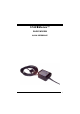
STAR Modem™ QUICK REFERENCE GUIDA RAPIDA GUIDE RAPIDE KURZANLEITUNG GUÍA RÁPIDA
DATALOGIC S.p.A. Via Candini, 2 40012 - Lippo di Calderara di Reno Bologna - Italy STARModem™ Ed.:06/2003 ALL RIGTHS RESERVED Datalogic reserves the right to make modifications and improvements without prior notification. Datalogic shall not be liable for technical or editorial errors or omissions contained herein, nor for incidental or consequential damages resulting from the use of this material.
CONTENTS Using STARModem™.............................................................................................. 2 Installation...................................................................................................................3 System Connections ................................................................................................... 3 RS232 Interface Connection ......................................................................... 4 Pen Emulation Interface Connection..
SOMMAIRE Utilisation de STARModem™ ................................................................................ 29 Installation................................................................................................................. 30 Connexion Systeme .................................................................................................. 30 Connexion RS232....................................................................................... 31 Connexion Emulation Crayon ..........
INDICE Utilización de los STARModem™ .......................................................................... 55 Instalación................................................................................................................. 56 Conexión del Sistema ............................................................................................... 56 Conexión RS232......................................................................................... 57 Conexión Emulación Lápiz.................
vi
STAR Modem™ RADIO MODEM QUICK REFERENCE 1
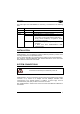
STARModem™ UK/US USING STAR Modem™ STARModem™ is a radio modem developed to provide wireless 433 MHz (European models) / 910 MHz (USA models) RF communication between any serial device (Host) and Datalogic RF devices or base stations, such as: - Gryphon™ M Readers - Dragon™ M Laser Scanners - STARModem™ Radio Modems - Formula Basic Line RF Terminals (F734-E/RF, F725-E/RF, F660-E/RF)* - STARGATE™ Base Stations * not compatible with STARModem™ USA models.
DATALOGIC UK/US The LEDs signal the STARModem™ functioning, as described in the following table: LED Power On TX/RX Status DESCRIPTION Green constant STARModem™ is powered. Yellow blinking STARModem™ is receiving or transmitting data. Off STARModem™ is working correctly. Red constant - at startup, after firmware upload, it indicates that the system is working with default configuration. - during normal functioning it signals a wrong connection to the Host.
STARModem™ UK/US RS232 INTERFACE CONNECTION Connect the modem cable directly to the PC COM Port. PEN EMULATION INTERFACE CONNECTION CAUTION Before proceeding with this connection, configure STARModem™ software parameters through the RS232 interface and then set the hardware jumper position (see "STARModem™ Configuration").
DATALOGIC UK/US WEDGE INTERFACE CONNECTION CAUTION Before proceeding with this connection, configure STARModem™ software parameters through the RS232 interface and then set the hardware jumper position (see "STARModem™ Configuration").
STARModem™ UK/US Screws Position 2 Position 1 Position 1 = RS232/Digital interface Position 2 = Wedge/Pen Emulation interface STARModem™ configuration can be performed in three ways: by using the DL Sm@rtSet software configuration program, by sending configuration strings from the Host via the RS232 interface or by reading configuration barcodes with a Datalogic RF device and sending the commands to STARModem™ via radio.
DATALOGIC UK/US Example Command programming sequence: $+ MA0RC1237 $- CR Carriage return character (0D Hex.) Exit and Save configuration STAR-Modem address in Stand Alone system: 1237 Enter configuration environment Each configuration parameter setting removes the condition previously active for that parameter. Refer to the STARModem™ Reference Manual for changing the default parameters.
STARModem™ UK/US INTERFACE SELECTION Select the desired interface string for your application, then set the correct hardware jumper position (see "STARModem™ Initial Setup" for jumper setting).
DATALOGIC CAUTION UK/US For changing the configuration parameters when using the Digital Terminal interface, send the new values via radio through Datalogic RF devices. Otherwise, send the $+CP0$-CR string via radio to set the RS232 interface and define the parameters via serial interface. This operation sets the RS232 parameters to default values and erases the current header and terminator selection.
UK/US STARModem™ SET RADIO ADDRESS Follow the procedure below to set the STARModem™ radio address and prepare it to transmit data to the destination device of the system: 1. Enter Configuration 2. Set STAR Modem™ Radio Address xxxx = four digits for the STARModem™ address (from 0000 to 1999). This address must be unique. 3. Address of the Stand Alone Destination Device xxxx = four digits for the address of the Stand Alone Destination Device (from 0000 to 1999). This address must be unique.
DATALOGIC UK/US SET RADIO ADDRESSES Follow the procedure below to set the STARModem™ radio address and prepare it to receive and transmit data to all devices included in the range from the First to the Last STAR-System™ destination device. 1. Enter Configuration 2. Set STAR Modem™ Radio Address xxxx = four digits for the STARModem™ address (from 0000 to 1999). This address must be unique. 3.
UK/US STARModem™ STAR Modem™ DEFAULT CONFIGURATION RS232 DEFAULT SETTINGS 9600 baud, parity disabled, 8 data bits, 1 stop bit, handshaking disabled, ACK/NACK protocol disabled, inter-character delay disabled, 5 sec. rx timeout, FIFO enabled, frame packing = frame + [CR]. PEN EMULATION DEFAULT SETTINGS Interpret operating mode, minimum output pulse 600 µs, conversion to Code 39, overflow medium, output level normal, idle level normal, inter-block delay disabled.
DATALOGIC UK/US TECHNICAL FEATURES Electrical Features 5 Volt Models 10 Volt Models Supply voltage Power consumption Indicators 5 Vdc ±5% 10 to 30 Vdc 2W Power On (green) TX/RX (yellow) Status (red) Radio Features European Models USA Models Working frequency Bit rate Effective Radiated Power Range (in open air) RF Modulation 433.92 Mhz Up to 19200 baud <10 mW 50 m / 164 ft 910 Mhz 36800 baud <1 mW 30 m / 98.
STARModem™ UK/US COMPLIANCE This device must be opened by qualified personnel only. Modifications or changes to this equipment without expressed written approval of Datalogic could void the authority to use the equipment. This device complies with PART 15 of the FCC Rules. Operation is subject to the following two conditions: (1) This device may not cause harmful interference, and (2) this device must accept any interference received, including interference which may cause undesired operation.
STAR Modem™ MODEM RADIO GUIDA RAPIDA 15
STARModem™ I STAR Modem™ - DESCRIZIONE E USO Il modem radio STARModem™ è stato sviluppato per fornire una comunicazione via radio a 433 MHz (modelli europei) / 910 MHz (modelli USA) tra un apparecchio seriale (es.
DATALOGIC I I LED segnalano il funzionamento dello STARModem™ come descritto nella seguente tabella: LED Power On TX/RX Status Verde acceso Giallo lampeggiante Spento Rosso acceso Rosso lampeggiante DESCRIZIONE STARModem™ è alimentato. STARModem™ sta ricevendo o trasmettendo dati. STARModem™ funziona correttamente - all'avvio successivo al caricamento del firmware, indica che il sistema sta lavorando con la configurazione di default.
STARModem™ I CONNESSIONE CON INTERFACCIA RS232 Collegate direttamente il cavo alla COM Port del vostro Host. CONNESSIONE CON INTERFACCIA PEN ATTENZIONE Prima di effettuare questa connessione, configurate i parametri software di STARModem™ attraverso l'interfaccia RS232; poi, posizionate correttamente il jumper (ponticello). Vedi la sezione "Configurazione di STARModem™".
DATALOGIC I Cavo Standard Datalogic per Wedge 90ACC1859 Adattatore STARModem™ CONFIGURAZIONE PRELIMINARE DI STAR Modem™ Per configurare correttamente STARModem™ occorre tenere presente le seguenti indicazioni. NOTA Utilizzando il modem per la prima volta, impostare l'indirizzo di STARModem™ desiderato via interfaccia seriale, poiché l'indirizzo predefinito alla consegna è "Undefined".
STARModem™ I DL Sm@rtSet DL Sm@rtSet è disponibile sul CD-ROM di STARModem™ e può essere installato sul PC. DL Sm@rtSet è un programma basato su Windows che consente di configurare in modo veloce ed intuitivo il modem utilizzando l'interfaccia RS232. Inoltre, permette di aggiornare il software sull'apparecchio connesso all'Host (vedi "DL Sm@rtSet User's Manual" per ulteriori informazioni).
DATALOGIC I CONFIGURAZIONE DI STAR Modem™ IN MODALITÀ STAND-ALONE STAR Modem™ Ricevitore (Server) RIPRISTINO DEL DEFAULT Se necessario, è possibile inviare la seguente stringa a STARModem™ attraverso l'interfaccia RS232 per ripristinare i valori di default: $+$*CR STAR Modem™ Default Questo comando non ripristina il valore STARModem™ e del parametro Baud Radio.
STARModem™ I Interfaccia Wedge IBM AT o PS/2 PCs $+CP500$-CR 2 IBM XT $+CP503$-CR 2 PC Notebook $+CP505$-CR 2 IBM SURE1 $+CP506$-CR 2 IBM Terminal 3153 $+CP504$-CR 2 IBM Terminals 31xx, 32xx, 34xx, 37xx Selezionate il codice KEY TRANSMISSION corretto (default = advanced keyboard). Se necessario, selezionate anche il KEYBOARD TYPE.
DATALOGIC I Se avete impostato l'interfaccia Wedge, dovreste anche inviare, fra la stringhe che seguono, la stringa per la selezione della Nazionalità della Tastiera: English $+FJ4$-CR Deutsch $+FJ3$-CR Svenskt $+FJ5$-CR Français $+FJ2$-CR Italiano $+FJ1$-CR USA $+FJ0$-CR Español $+FJ6$-CR Belge $+FJ7$-CR STAR Modem™ Trasmettitore (Client) RIPRISTINO DEL DEFAULT Se necessario, è possibile inviare la seguente stringa a STARModem™ attraverso l'interfaccia RS232 per ripristinare i valori d
STARModem™ I CONFIGURAZIONE DI STAR Modem™ IN MODALITÀ STAR-System™ RIPRISTINO DEL DEFAULT Se necessario, è possibile inviare la seguente stringa a STARModem™ attraverso l'interfaccia RS232 per ripristinare i valori di default: STAR Modem™ Default $+$*CR Questo comando non ripristina il valore di default dell'indirizzo di STARModem™, degli indirizzi degli apparecchi destinatari e del parametro Baud Radio.
DATALOGIC I STAR Modem™ - CONFIGURAZIONE DI DEFAULT CONFIGURAZIONE INTERFACCIA RS232 9600 baud, parità disabilitata, 8 bit di dato, 1 bit di stop, handshaking disabilitato, protocollo ACK/NACK disabilitato, ritardo intercarattere disabilitato, timeout ricezione 5 sec., FIFO abilitato, frame packing = frame + [CR].
STARModem™ I CARATTERISTICHE TECNICHE Caratteristiche Elettriche Modelli 5 Volt Modelli 10-30 Volt Tensione di alimentazione Potenza assorbita in carica Indicatori 5 Vdc ±5% da 10 a 30 Vdc Caratteristiche Radio Frequenza di lavoro Bit rate Potenza effettiva emessa Portata (in assenza di ostacoli) RF Modulazione 2W Power On (verde) TX/RX (giallo) Status (rosso) Modelli europei Modelli USA 433.
DATALOGIC I CONFORMITÀ Questo apparecchio può essere aperto solo da personale qualificato. STARModem™ è un apparecchio Classe III in conformità con la norma EN-60950 Electrical Safety Standard. Deve essere alimentato con un'unità di alimentazione Classe 2 avente una tensione di alimentazione di 5 Vdc ±5% per i modelli 5 Volt e un'alimentazione compresa tra 10 - 30 Vdc per i modelli 10-30 Volt. Il cavo deve avere una lunghezza < 3m.
STAR Modem™ MODEM RADIO GUIDE RAPIDE 28
DATALOGIC F UTILISATION DE STAR Modem™ STARModem™ est un modem radio qui permet la communication par radio (433 MHz pour les modèles européens et 910 MHz pour les modèles USA) depuis un appareil sériel (par ex.
STARModem™ F Les indicateurs signalent le fonctionnement de STARModem™, comme indiqué dans le tableau suivant: INDICATOR Power On Vert permanent TX/RX Jaune clignotant Status DESCRIPTION STARModem™ est alimenté. STARModem™ reçoit ou transmet les données. STARModem™ fonctionne correctement. Désactivé Rouge permanent - au démarrage suivant le chargement du microprogramme (firmware), il signale que le système utilise la configuration par défaut.
DATALOGIC F CONNEXION RS232 Branchez le câble directement dans le port COM du PC. CONNEXION EMULATION CRAYON ATTENTION Avant de réaliser cette connexion, vous devez configurer les paramètres du software STARModem™ via l'interface RS232 et puis positionner le cavalier (jumper) correctement (se référer à la section " Configuration STARModem™ ").
STARModem™ F CONNEXION INTERCLAVIER ATTENTION Avant de réaliser cette connexion, vous devez configurer les paramètres du software STARModem™ via l'interface RS232 et puis positionner le cavalier (jumper) correctement (se référer à la section " Configuration STARModem™ ").
DATALOGIC F Vis Position 2 Position 1 Position 1 = Interface RS232/Digital Position 2 = Interface Interclavier/Emulation Crayon STARModem™ peut être configuré de trois façons: en utilisant le programme de configuration DL Sm@rtSet, en envoyant les séquences de configuration depuis le Host via l'interface RS232 ou en lisant les codes à barres de configuration avec les appareils radio Datalogic et en les envoyant à STARModem™ par radio.
STARModem™ F Exemple Séquence d'une commande de programmation: $+ MA0RC1237 $- CR Charactère carriage return (0D Hex.) Fin et enregistrement de la configuration Adresse de STARModem™ dans système Stand Alone: 1237 Initialisation de la configuration La configuration d'un paramètre remplace la condition qui était active précédemment. Se référer au STARModem™ Reference Manual pour changer les paramètres par défaut.
DATALOGIC F SELECTION DE L'INTERFACE Envoyez la chaîne de programmation correspondant au mode de communication désiré, puis placez le cavalier correctement (voir la section "Configuration STARModem™" pour plus de détails relatifs à l'installation du cavalier).
F STARModem™ Pour changer les paramètres de configuration en utilisant l'interface Digital terminal, envoyez les nouvelles valeurs au moyen des appareils radio Datalogic par radio. Autrement, envoyer la chaîne $+CP0$-CR par radio pour sélectionner l'interface RS232 et configurer les paramètres via l'interface RS232. Cette opération restaure les paramètres de l'interface RS232 par défaut et annule la sélection du "header" et du "terminator".
DATALOGIC F SELECTION DE L'ADRESSE RADIO En suivant la procédure ci-dessous, vous pouvez configurer le STARModem™ pour transmettre les données à l’appareil Stand Alone destinataire du système: 1. Initialisation de la Configuration 2. Enregistrement de l'Adresse Radio de STAR Modem™ xxxx = quatre chiffres pour l'adresse de STARModem™ ( de 0000 à 1999). Cette adresse doit être unique. MA0RCxxxx 3.
STARModem™ F SELECTION DES ADRESSES RADIO En suivant la procédure ci-dessous, vous pouvez configurer le STARModem™ pour recevoir ainsi que transmettre les données aux appareils inclus dans la plage d’adresses définie entre le premier et le dernier appareil destinataire STAR-System™. 1. Initialisation de la Configuration 2. Enregistrement de l'Adresse Radio de STAR Modem™ xxxx = quatre chiffres pour l'adresse de STARModem™ (de 0000 à 1999). Cette adresse doit être unique. MA1RCxxxx 3.
DATALOGIC F STAR Modem™ - CONFIGURATION PAR DEFAUT CONFIGURATION INTERFACE RS232 9600 baud, parité désactivé, 8 bit de données, 1 bit de stop, "handshaking" désactivée, ACK/NACK depuis l’host désactivé, délai entre les caractères désactivé, "rx timeout" 5 sec.
STARModem™ F CARACTERISTIQUES TECHNIQUES Caractéristiques Électriques Tension Consommation Indicateurs Caractéristiques Radio Fréquence de fonctionnement Transmission de données Energie réelle émise Portée Modulation RF Modèles 5 Volt Modèles 10-30Volt 5 Vdc ±5% 10 à 30 Vdc 2W Power On (vert) TX/RX (jaune) Status (rouge) Modèles européens Modèles USA 433.
DATALOGIC F CONFORMITE L'appareil ne doit être ouvert que par une personne qualifiée. STARModem™ est un appareil de Class III selon la norme EN-60950 Electrical Safety Standard. La tension a un valeur de 5 Vdc ±5% pour les modèles 5 Volt et est comprise dans la plage de valeurs 10-30 Vdc pour les modèles 10-30 Volt. L'appareil doit être connecté à un boîtier d'alimentation de Classe 2 avec une longueur du câble < 3 m.
STAR Modem™ RADIO MODEM KURZANLEITUNG 42
DATALOGIC D BESCHREIBUNG UND GEBRAUCHSANWEINSUNG STARModem™ ist ein Funkmodem, und bietet eine zuverlässige 433 MHz (Europäische Modelle) / 910 MHz (USA Modelle) Funkverbindung für Datenübertragung zwischen einem seriellen Gerät (PC) und Datalogic Basisstationen oder mobile Geräte wie zum Beispiel: - Gryphon™ M Lesegerät - Dragon™ M Laserscanner - STARModem™ Funk Modem - Formula Basic Line RF Laserterminal (F734-E/RF, F725-E/RF, F660-E/RF)* - STARGATE™ Basisstation * nicht kompatible mit STA
STARModem™ D Die LED-Anzeigen zeigen den Zustand des STARModem™. Siehe dazu folgende Tabelle: LED Power On TX/RX Status ZUSTAND grün gelb blinkend aus rot ein STARModem™ ist versorgt. STARModem™ sendet / empfängt Daten. Kein Fehler - rot blinkend - beim Start nach dem Ladevorgang der Firmware zeigt die LED, dass die Konfiguration auf die Grundeinstellungen gesetzt wird. beim Normalbetrieb zeigt die LED, dass der Anschluss zum PC nicht richtig ist. die LED zeigt die Ausführung eines Kommandos.
DATALOGIC D RS232 - SCHNITTSTELLE Stecken Sie das Kabel direkt am PC COM Port ein. LESESTIFTSCHNITTSTELLE ACHTUNG Vor der Modemsinstallation sollten die Software Parameter über RS232 Schnittstelle festgelegt werden. Der Jumper sollte in die korrekte Position gesteckt werden (siehe Abschnitt "STARModem™ Konfiguration"). Der Adapter erlaubt den Anschluss an den Host über die Lesestiftschnittstelle.
STARModem™ D Der Adapter erlaubt den Anschluss an den Host über die Tastaturschnittstelle. Siehe dazu das folgende Bild: Datalogic Standard Tastaturschnittstellen-Kabel 90ACC1859 STARModem™ Adapter STAR Modem™ ANFANGSKONFIGURATION Beachten Sie die folgenden Richtlinien zur korrekten STARModem™ Konfiguration: NOTE Beim ersten Gebrauch, sollten Sie die gewünschte STARModem™ Adresse über die RS232 Schnittstelle festlegen, da die Factory-Default Adresse des Modems undefieniert ist.
DATALOGIC D Die STARModem™ Konfiguration kann auf drei Wegen erfolgen: die Parameter werden mit der Software DL Sm@rtSet festgelegt, die Konfigurationsstrings werden über die serielle Schnittstelle an das Modem gesendet, oder die Konfigurationscodes werden mit einem Funklesegerät gelesen und an das Modem gesendet. DL Sm@rtSet DL Sm@rtSet ist verfügbar auf der STARModem™ CD and kann auf dem PC installiert werden.
STARModem™ D STAR MODEM™ STAND-ALONE-MODE KONFIGURATION FÜR STAR Modem Empfänger (Server) GRUNDEINSTELLUNG Falls nötig, senden Sie die folgende Zeichenfolge über die serielle Schnittstelle an das Modem um es auf die Grundeinstellungen zurückzusetzen. $+$*CR STAR Modem™ Grundeinstellung Dieser Befehl setzt weder die Adresse des Modems noch den Funk Baud Parameter nicht auf die Grundeinstellung zurück.
DATALOGIC D Tastaturschnittstelle IBM AT oder PS/2 PCs $+CP500$-CR 2 IBM XT $+CP503$-CR 2 PC Notebook $+CP505$-CR 2 IBM SURE1 $+CP506$-CR 2 IBM Terminal 3153 $+CP504$-CR 2 IBM Terminals 31xx, 32xx, 34xx, 37xx Wählen Sie den korrekten Übertragungsmode. Falls nötig, lesen Sie den Tastaturtyp-Zeichenfolge: (default = advanced keyboard).
STARModem™ D Wenn Sie die Tastaturschnittstelle gewählt haben, Tastaturnationalität bestimmen, die Ihrer Tastatur entspricht: sollten Sie English $+FJ4$-CR Deutsch $+FJ3$-CR Svenskt $+FJ5$-CR Français $+FJ2$-CR Italiano $+FJ1$-CR USA $+FJ0$-CR Español $+FJ6$-CR Belge $+FJ7$-CR die STAR Modem Transmitter (Client) GRUNDEINSTELLUNG Falls nötig, senden Sie die folgende Zeichenfolge über die serielle Schnittstelle an das Modem um es auf die Grundeinstellungen zurückzusetzen.
DATALOGIC D Es ist keine Schnittstelleneinstellung notwendig, weil das STARModem™ nur die serielle Schnittstelle zur Datenübertragung nutzt. STAR Modem™ KONFIGURATION STAR-SYSTEM™ MODE FÜR GRUNDEINSTELLUNG Falls nötig, senden Sie die folgende Zeichenfolge über die serielle Schnittstelle an das Modem um es auf die Grundeinstellungen zurückzusetzen.
D STARModem™ Beim Einstellen eines Bereichs von Ziel-Gerätesadressen, beginnt das STARModem™ mit dem Roaming nach Geräten, die in diesem Bereich enthalten sind. Es ist keine Schnittstelleneinstellung notwendig wenn STAR-System™ die serielle Schnittstelle zur Datenübertragung nutzt. STAR Modem™ GRUNDEINSTELLUNG RS232 - GRUNDEINSTELLUNG 9600 Baud, keine Parität, 8 Datenbits, 1 Stopbit, kein Handshake, kein ACK/NACK vom Host, keine Verzögerungszeit zwischen den Zeichen, 5 sek.
DATALOGIC D TECHNISCHE DATEN Elektrische Daten Stromversorgung Stromverbrauch Anzeigen Funkdaten Funkfrequenz Bit rate Funkleistung Reichweite im freien Feld RF Modulation Modelle 5 Volt Modelle 10-30 Volt 5 Vdc ±5% 10 bis 30 Vdc 2W Power On (grün) TX/RX (gelb) Status (rot) Europäische Modelle USA Modelle 433.92 Mhz bis 19200 baud <10 mW 50 m 910 Mhz 36800 baud <1 mW 30 m FSK Konfiguration des Systems Max.
STAR Modem™ RADIO MODEM GUÍA RÁPIDA 54
DATALOGIC E UTILIZACION DE LOS STAR Modem™ STARModem™ es un modem radio desarrollado para la comunicacíon (433 MHz para modelos europeos y 910 MHz para modelos de US) sin cable entre un terminal serie (Host) y terminales RF de Datalogic o estaciones base como: - Lectores Gryphon™ M - Pistolas Láser Dragon™ M - Radio Modems STARModem™ - Terminales Formula Basic Line RF (F734-E/RF, F725-E/RF, F660-E/RF)* - Estaciones Base STARGATE™ * no compatibles con los modelos de US del STARModem™.
STARModem™ E Los LEDs señalan el estado de los modem, como se describe a continuación: LED Power On TX/RX Status DESCRIPCIÓN Verde fijo STARModem™ está encendido. Amarillo parpadeante STARModem™ está recibiendo o enviando datos. Off STARModem™ funciona correctamente. Rojo fijo - al encenderse después de cargar el firmware, indica que el sistema funciona con la configuración estándar por defecto. - durante el normal funcionamiento, indica una conexión errónea con el Host.
DATALOGIC E CONEXIÓN RS232 Conectar el cable del modem directamente al Puerto del PC COM. CONEXIÓN EMULACIÓN LÁPIZ CUIDADO Antes de empezar la conexión, configure los parámetros software del STARModem™ mediante el interface RS232 y después ponga la posición del jumper hardware (ver "Configuración STARModem™ ").
STARModem™ E Para la conexión del interface de Emulación Teclado, es necesario utilizar el adaptador según se muestra en la figura inferior: Cable estándar Datalogic para Emulación Teclado 90ACC1859 Adaptador STARModem™ CONFIGURACIÓN INICIAL DEL STAR Modem™ Para una correcta configuración del STARModem™ hay que tener en cuenta los siguientes puntos: NOTA Cuando se use el modem por primera vez, ponga la dirección deseada del STARModem™ a través del interface serie RS232, ya que la dirección está
DATALOGIC E Tornillos Posición 2 Posición 1 Posición 1 = interfaz RS232/Digital Posición 2 = interfaz Emulación Teclado/Emulación Lápiz La configuración de los STARModem™ puede efectuarse de tres maneras: mediante el programa software de configuración de DL Sm@rtSet, enviando las cadenas de configuración desde el Host vía el interface RS232 o leyendo los códigos de barras de configuración con el terminal Datalogic RF y enviando los comandos al STARModem™ vía radio.
STARModem™ E Ejemplo Secuencia comando de programación: $+ MA0RC1237 $- CR Caracter tecla retroceso (0D Hex.) Fin y grabación de la configuración Dirección STAR-Modem en Stand Alone system:1237 Inicialización de la configuration Cada ajuste de los parámetros de configuración elimina la condición activa anterior para ese parámetro. Ver el Manual de Referencias del STARModem™ para cambiar los parámetros que vienen de fábrica.
DATALOGIC E 1. Inicialización de la Configuración 2. Ponga la dirección de Radio STAR Modem™ xxxx = cuatro cifras para dirección STARModem™ (de 0000 a 1999). Esta dirección debe ser única. 3. Selección del Baudio Radio (no válido para modelos de US) x = 0 por 9600 baudios 1 por 19200 baudios MFx 4.
STARModem™ E ALT MODE La selección de la interfaz siguiente permite una interpretación correcta del PC de los códigos de barras transmitidos, independientemente de la selección de la nacionalidad del teclado. No es necesita efectuar la selección de la nacionalidad del teclado. (default = Num Lock Unchanged) Por favor, verifiquen que el teclado numérico este activado en su teclado.
DATALOGIC E STAR Modem™ Transmisor (Cliente) RESTAURAR VALORES DADOS DE FÁBRICA Cuando sea necesario, enviar la siguiente cadena al STARModem™ via RS232 para restaurar los valores dados de fábrica: Configuración STAR Modem™ predefinida $+$*CR Este comando no restaura la dirección del STARModem™, la dirección del dispositivo de destino Stand-Alone ni el parámetro Baudio Radio a sus valores predefinidos.
STARModem™ E CONFIGURACIÓN DEL STAR MODEM™ EN MODO DE CONFIGURACIÓN STAR-SYSTEM™ RESTAURAR VALORES DADOS DE FÁBRICA Cuando sea necesario, enviar la siguiente cadena al STARModem™ via RS232 para restaurar los valores dados de fábrica: Configuración STAR Modem™ predefinida $+$*CR Este comando no restaura la dirección del STARModem™, la dirección de los dispositivos de destino STAR-System™ ni el parámetro Baudio Radio a sus valores predefinidos.
DATALOGIC E Definiendo una serie de direcciónes por los dispositivos de destino, STARModem™ activa el Roaming en los dispositivos incluidos en esta serie. No se necesita seleccionar un interface, ya que todas las transmisiones STAR-System™ se realizan vía un interface serie.
STARModem™ E GARANTIA Datalogic garantiza este producto contra todos los defectos de manejo y de materiales, por un periodo de 24 meses desde la fecha de envio, sabiendo que el producto funciona y esta en perfectas condiciones. Datalogic tiene el derecho de reparar o reemplezar el producto sin que eso suponga una prolongación de la garantía original. La garantía no será valida si el producto ha sufrido abuso, daños accidentales, reparaciones no autorizadas o falsificado.
DATALOGIC E CONFORMIDAD Este dispositivo debe ser abierto por una persona cualificada. STARModem™ es un equipo de Clase III según el Estándar de Seguridad Eléctrica EN-60950. Este aparado debe suministrarse cin la unidad de alimentación marcada "Class 2" con potencia de salida de 5 Vdc ±5% para los modelos 5 Volt, y de 10 - 30 Vdc para los modelos 10-30 Volt con un cable de < 3m de longitud.
ANTENNA Position A (standard) Position B MOUNTING BRACKETS ST-217 mounting bracket 68 ST-133 mounting bracket
OVERALL DIMENSIONS 6.7 84 3.3 170.7 mm inch 7.6 0.39 68 32.7 1.3 2.7 9 0.35 7.8 0.3 4.2 0.16 = 50 = R 42 16.5 = 1.96 = 40 73 2.87 = 40 = = 1.57 = 90° 30 1.18 13.8 0.54 17.5 0.68 15 0.59 26 1.02 1x45° n° 2 2.5 0.09 32 1.26 4.2 6 0.1 20° 4.5 n. 2 0.17 n. 2 .25 R2 25 0.98 3 0.11 2.5 0.09 46 1.81 R1 4.2 n °2 0.16 n° 2 7.5 0.29 R2.2 23 0.9 5 = 35 = = 1.
STAR Modem™ CABLE PINOUT 1 5 9 6 STAR Modem™ 9-pin female connector Pin 1 2 3 4 5 6 7 8 RS232 Wedge Pen PC_DATA TX232 RX232 GND CTS232 RTS232 KB_DATA + 5 Vdc (Keyboard Supply Voltage) GND PC_CLK KB_CLK KB_DATA PWR GND Power Supply / Alimentazione / Alimentation / Netzteil / Alimentación Pin 5 9 NOTE Name GND VDC+ (Modem Supply Voltage) By inserting the power supply connector in the power jack, pin 9 is not connected.
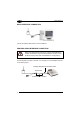
TYPICAL LAYOUT APPLICATIONS DRAGON 1 DRAGON 2 Modem DRAGON 3 HOST PC F734-E Stand Alone Mode - STAR MODEM™ Server Connected to Host PC 433 MHz/910MHz RF Connection DRAGON 5 Volt Modem 2.
STARGATE 2 STARGATE 3 Modem SCANNER STARGATE 1 HOST STAR-System™ Mode - STAR MODEM™ Transmitting Data from Scanner to STAR-System™ STARGATE 3 STARGATE 2 [ENQ] [ENQ] STARGATE 1 Data Modem Data PRINTER Data HOST STAR-System™ Mode - STAR MODEM™ Receiving Data from STAR-System™ for Printer 72
Modem 1 Modem 2 HOST 1 HOST 2 STAR-System™ Mode – Bi-directional Communication 73
DATALOGIC S.p.A.