GRYPHON™ BT SH3500 REFERENCE MANUAL
DATALOGIC S.p.A. Via Candini 2 40012 - Lippo di Calderara di Reno Bologna - Italy GRYPHON™ BT SH3500 Ed.: 05/2005 This manual refers to software version 1.00 and later. ALL RIGHTS RESERVED Datalogic reserves the right to make modifications and improvements without prior notification. Datalogic shall not be liable for technical or editorial errors or omissions contained herein, nor for incidental or consequential damages resulting from the use of this material.
CONTENTS GENERAL VIEW ......................................................................................... vi COMPLIANCE ............................................................................................ vii LED CLASS............................................................................................... viii 1 INTRODUCTION .......................................................................................... 1 2 2.1 2.2 2.3 2.4 GRYPHON™ BT SH3500 POWER .........................
Caps Lock ................................................................................................... 23 Caps Lock Auto-Recognition (IBM AT compatible only) .............................. 23 DATA FORMAT.......................................................................................... 24 Header ........................................................................................................ 25 Terminator...................................................................................
7 TROUBLESHOOTING................................................................................ 58 8 8.1 8.2 8.3 8.4 TECHNICAL FEATURES ........................................................................... 59 Gryphon™ BT SH3500 ............................................................................... 59 om-GRYPHON™ BT SH3500..................................................................... 60 Status Indicators ..............................................................................
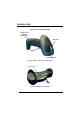
GENERAL VIEW GRYPHON™ BT SH3500 READER Gryphon™ BT SH3500 Battery Cover Blue LED Trigger Reading window Figure A – Gryphon™ BT SH3500 Series Reader Gun searcher LEDs Figure B – OM-Gryphon™ BT SH3500 vi
COMPLIANCE This device must be opened by qualified personnel only. The batteries must be removed before opening the device. Modifications or changes to this equipment without the expressed written approval of Datalogic could void the authority to use the equipment. This device complies with PART 15 of the FCC Rules.
LED CLASS TO EN60825-1:(2001) viii
INTRODUCTION 1 1 INTRODUCTION Datalogic has moved a step ahead in the concept of “instinctive reading". The new Gryphon™ BT SH3500 reader series has been developed to provide optimised reading performance through excellent ergonomic design, a natural instinctive reading approach and innovative good reading feedback. ® The Gryphon™ BT SH3500 (Gryphon™ Bluetooth ) reader is a CCD wireless barcode scanner communicating in the 2.4 GHz ISM band and using the Serial Port ® ® Profile (SPP).
GRYPHON™ BT SH3500 2 2 GRYPHON™ BT SH3500 POWER To begin using your Gryphon™ BT SH3500 reader you must charge the Gryphon™ BT SH3500 battery using OM-Gryphon™ BT SH3500 as described in par. 2.3. A full charge takes less than 4 hours with Li-Ion batteries. 2.1 POWERING THE OM-GRYPHON™ BT SH3500 Connections should always be made with power off! CAUTION Apply power to OM-Gryphon™ BT SH3500 by connecting a power supply unit to the connector on the base of the cradle.
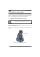
GRYPHON™ BT SH3500 POWER 2.2 2 BATTERY TYPE You can install Li-Ion batteries in the Gryphon™ BT SH3500. 2.3 BATTERY CHARGING Once the system is connected and powered, you can place the Gryphon™ BT SH3500 onto the cradle to charge the battery. Charging the Batteries Gun searcher Power on / Data (yellow LED) Charging (red LED) A SCH RGE DI Charge completed (green LED) When the reader is correctly placed onto the cradle, the red LED on the cradle goes on to indicate that the battery is charging.
GRYPHON™ BT SH3500 2 The LEDs positioned on the cradle signal the charge status, as described in the following table: LED STATUS Yellow On = OM-Gryphon™ is powered. Power on / Yellow Blinking = OM-Gryphon™ receives commands from Data the Host. 4 Charging Red On = the battery charge is in progress. Red Blinking = the battery reconditioning is in progress. Charging completed Green On = the battery is completely charged.
GRYPHON™ BT SH3500 POWER 2.4 2 REPLACING GRYPHON™ BT SH3500 BATTERIES To change the batteries in your GRYPHON™ BT SH3500 scanner, proceed as follows: Battery cover screw 1. Unscrew the battery cover screw. 2. Open the battery cover. Battery cover 3. Replace the old battery pack with new one, then screw the battery cover back into place. Li-Ion Battery Pack CAUTION Dispose of used batteries properly. Do not disassemble, modify, heat or throw batteries into fire.
GRYPHON™ BT SH3500 3 3 GRYPHON™ BT SH3500 OPERATION 3.1 BLUETOOTH® DEFINITIONS Bluetooth address: ® a unique 12-character hexadecimal, IEEE 48-bit ® address (BT_ADDR) that represents a Bluetooth device. ® A sub-system containing Bluetooth RF, baseband, resource controller, link manager, device manager, ® and Bluetooth HCI. Bluetooth device: ® a device that is capable of short-range wireless ® communication using the Bluetooth system. BT: abbreviation for Bluetooth .
GRYPHON™ BT SH3500 OPERATION 3.2 3 BLUETOOTH® RADIO CONNECTION During typical operation a physical radio channel is shared by a group of devices that are synchronized to a common clock and frequency hopping pattern. One device provides the synchronization reference and is known as the Master. All other devices are known as Slaves. A group of devices synchronized in this fashion form a piconet. ® Most Bluetooth devices can be both Master or Slave.
GRYPHON™ BT SH3500 3 3.3 OM-GRYPHON™ BT SH3500 CABLE CONNECTIONS The OM-Gryphon™ BT SH3500 incorporates a multi-standard interface which can be connected to a Host by simply plugging an RS232, USB or Wedge emulation cable into the Host connector, placed on the base of the cradle. In addition the cradle must be connected to an external power supply. To connect the OM-Gryphon™ BT SH3500: 1.
GRYPHON™ BT SH3500 OPERATION 3.4 3 RS232 CONNECTION OM-Gryphon™ BT SH3500 Host RS232 3.5 USB CONNECTION OM-Gryphon™ BT SH3500 Host USB 3.
GRYPHON™ BT SH3500 4 4 CONFIGURATION 4.1 4.1.1 CONFIGURATION METHOD Reading Configuration Barcodes This manual can be used for complete setup and configuration of your reader by following the setup procedures in this chapter (see par. 4.2 for an overview). If you wish to change the default settings, this manual provides complete configuration of your reader in an easy way.
CONFIGURATION 4.2 4 SETUP PROCEDURE Follow the given procedure to set up Gryphon™ BT SH3500. Read the restore default parameters code below. 1. Restore Gryphon™ BT SH3500 Default i i i 2. Pk Pk Pk Read the Bind code to pair the Gryphon™ BT SH3500 to the OM-Gryphon™ BT SH3500 cradle. The reader is dedicated to the cradle. Any previously bound reader will be excluded.
GRYPHON™ BT SH3500 4 4.3 1. RS232 INTERFACE SELECTION Read the OM-Gryphon™ BT SH3500 restore default code: Restore OM-Gryphon™ BT SH3500 Default i i i 39 Rk 39 Rk 39 Rk 2. Read the RS232 interface selection code: RS232 i i i 4.4 1. $1 k $1 k $1 k WEDGE INTERFACE SELECTION Read the OM-Gryphon™ BT SH3500 restore default code: Restore OM-Gryphon™ BT SH3500 Default i i i 39 Rk 39 Rk 39 Rk 2.
CONFIGURATION 4.5 4 USB INTERFACE CONFIGURATION AND SELECTION The USB interface is compatible with: Windows 98 (and later) Mac OS 8.0 (and later) IBM POS for Windows 4690 Operating System USB START-UP As with all USB devices, upon connection, the Host performs several checks by communicating with the OM-Gryphon™ BT SH3500. Before the OM-Gryphon™ BT SH3500 is ready, the correct USB driver must be loaded.
GRYPHON™ BT SH3500 4 4.5.1 USB Interface Selection USB USB-KBD (default) i i i 6" k 6" k 6" k i i i 6" k 6" k 6" k USB-COM* * When configuring USB-COM, the relevant files and drivers must be installed from the USB Device Installation software which can be downloaded from the web page (see http://www.datalogic.com). 4.6 CHANGING DEFAULT SETTINGS Once your reader is setup, you can change the default parameters to meet your application needs.
RS232 PARAMETERS BAUD RATE PARITY DATA BITS STOP BITS 1. Read the Enter Configuration code ONCE, available at the top of each page. 2. Read configuration codes from the desired groups. ☞ = Read the code and follow the procedure given = Default value 3. Read the Exit and Save Configuration code ONCE, available at the top of each page.
Enter configuration i i k k Exit and Save Configuration RS232 i i k k BAUD RATE 150 baud i$% 6k i$% 6k i$% 6k 300 baud i$% 9k i$% 9k i$% 9k 600 baud i$%
Enter configuration i i k k Exit and Save Configuration RS232 i i k k PARITY none i$$ 4k i$$ 4k i$$ 4k even parity i$$ 7k i$$ 7k i$$ 7k odd parity i$$ :k i$$ :k i$$ :k DATA BITS 7 bits i$" 0k i$" 0k i$" 0k 8 bits i$" 3k i$" 3k i$" 3k 9 bits i$" 6k i$" 6k i$" 6k 17
Enter configuration i i k k Exit and Save Configuration RS232 STOP BITS 1 stop bit i$# 2k i$# 2k i$# 2k 2 stop bits i$# 5k i$# 5k i$# 5k 18 i i k k
USB USB-KBD Keyboard nationality 1. Read the Enter Configuration code ONCE, available at the top of each page. 2. Read configuration codes from the desired groups. ☞ = Read the code and follow the procedure given = Default value 3. Read the Exit and Save Configuration code ONCE, available at the top of each page.
Enter configuration i i k k Exit and Save Configuration USB i i k k KEYBOARD NATIONALITY This parameter default value is restored through the Interface Selection code and not Restore Default.
WEDGE PARAMETERS KEYBOARD NATIONALITY CAPS LOCK CAPS LOCK AUTO-RECOGNITION 1. Read the Enter Configuration code ONCE, available at the top of each page. 2. Read configuration codes from the desired groups. ☞ = Read the code and follow the procedure given = Default value 3. Read the Exit and Save Configuration code ONCE, available at the top of each page.
Enter configuration i i k k Exit and Save Configuration WEDGE i i k k KEYBOARD NATIONALITY Belgian i'+ Zk i'+ Zk i'+ Zk English i'+ Qk i'+ Qk i'+ Qk French i'+ Kk i'+ Kk i'+ Kk German i'+ Nk i'+ Nk i'+ Nk Italian i'+ Hk i'+ Hk i'+ Hk Spanish i'+ Wk i'+ Wk i'+ Wk Swedish i'+ Tk i'+ Tk i'+ Tk USA i'+ Ek i'+ Ek i'+ Ek The Japanese Keyboard Nationality selection is valid only for IBM AT compatible PCs.
Enter configuration i i k k Exit and Save Configuration WEDGE i i k k CAPS LOCK caps lock OFF i'& ;k i'& ;k i'& ;k caps lock ON i'& >k i'& >k i'& >k Select the appropriate code to match your keyboard caps lock status. Note: For IBM AT and PC Notebook interface selections, the caps lock status is automatically recognized, therefore this command is not necessary.
DATA FORMAT HEADER TERMINATOR 1. Read the Enter Configuration code ONCE, available at the top of each page. 2. Read configuration codes from the desired groups. ☞ = Read the code and follow the procedure given = Default value 3. 24 Read the Exit and Save Configuration code ONCE, available at the top of each page.
Enter Configuration i i Exit and Save Configuration k k i i DATA FORMAT k k HEADER no header i&" i&" i&" k k k two character header ☞ ☞ ☞ i&" k i&" k i&" k five character header ☞ i&" #k i&" #k i&" #k eight character header i&" k i&" k i&" k three character header i&" k i&" k i&" k six character header ☞ ☞ i&" k i&" k i&" k four character header ☞ one character header i&" k i&" k i&" k seven character header ☞ i&" 'k i&" 'k i&"
Enter Configuration i i Exit and Save Configuration k k DATA FORMAT i i k k TERMINATOR no terminator i&" k i&" k i&" k one character terminator ☞ two character terminator ☞ i&" k i&" k i&" k three character terminator ☞ four character terminator ☞ i&" k i&" k i&" k ☞ i&" &k i&" &k i&" &k i&" "k i&" "k i&" "k seven character terminator ☞ eight character terminator ☞ i&" k i&" k i&" k five character terminator six character terminator ☞ i&"
READING PARAMETERS HAND-HELD OPERATION FLASH MODE BEEPER INTENSITY BEEPER TONE BEEPER TYPE BEEPER LENGTH 1. Read the Enter Configuration code ONCE, available at the top of each page. 2. Read configuration codes from the desired groups. ☞ = Read the code and follow the procedure given = Default value 3. Read the Exit and Save Configuration code ONCE, available at the top of each page.
Enter Configuration i i k k Exit and Save Configuration i i READING PARAMETERS k k HAND-HELD OPERATION hardware trigger i#, Fk i#, Fk i#, Fk software trigger i#, Ck i#, Ck i#, Ck FLASH MODE "FLASH" ON duration ☞ i## 1k i## 1k i## 1k "FLASH" OFF duration ☞ i## 4k i## 4k i## 4k Read 2 numbers in the range 01-99: 01 to 99 = from .1 to 9.9 seconds. Flash-ON = 1 sec. Flash-OFF = 0.
Enter Configuration i i k k Exit and Save Configuration READING PARAMETERS i i k k BEEPER INTENSITY * very low intensity i#( ;k i#( ;k i#( ;k low intensity i#( >k i#( >k i#( >k medium intensity i#( Ak i#( Ak i#( Ak high intensity i#( Dk i#( Dk i#( Dk * This sets the beeper OFF for data entry, while for all other beeper signals it has the meaning very low intensity. The Intensity parameter is effective for all operating conditions described in par. 8.3.
Enter Configuration i i k k Exit and Save Configuration READING PARAMETERS i i k k BEEPER TYPE monotone i#+ Ak i#+ Ak i#+ Ak bitonal i#+ Dk i#+ Dk i#+ Dk BEEPER LENGTH long i#* ?k i#* ?k i#* ?k short i#* Bk i#* Bk i#* Bk 30
CODE SELECTION EAN/UPC FAMILY 2/5 FAMILY CODE 39 FAMILY CODE 128 FAMILY CODABAR FAMILY CODE 93 MSI PLESSEY TELEPEN DELTA IBM CODE 11 CODE 16K CODE 49 RSS FAMILY 1. 2. Read the Enter Configuration code ONCE, available at the top of each page. Read configuration codes from the desired groups. ☞ = Read the code and follow the procedure given = Default value 3. Read the Exit and Save Configuration code ONCE, available at the top of each page.
Enter Configuration i i Exit and Save Configuration k k CODE SELECTION i i k k DISABLE ALL CODE FAMILIES i"; `k i"; `k i"; `k The reader allows up to 5 code selections. This does not limit the number of CODES enabled to 5, as it depends on the code family. NOTE SINGLE SELECTIONS = • ONE combination code from the EAN family • ONE code from the 2/5 family Example 5 code selections: 1. 2/5 Interleaved 2. 2/5 Industrial 3. Code 128 + EAN 128 4. Code 39 Full ASCII + Code 32 5.
Enter Configuration i i k k Exit and Save Configuration CODE SELECTION i i k k EAN/UPC FAMILY disable the family i"" .k i"" .k i"" .k Read the desired family code Note: Since the EAN/UPC without ADD ON code selection is enabled by default, to correctly enable another selection, first disable the family.
Enter Configuration i i k k Exit and Save Configuration CODE SELECTION i i WITH ADD ON 2 AND 5 EAN 8/EAN 13/UPC A/UPC E i"" =k i"" =k i"" =k EAN 8/EAN 13 i"" @k i"" @k i"" @k UPC A/UPC E i"" Ck i"" Ck i"" Ck WITH ADD ON 2 ONLY EAN 8/EAN 13 i"", k i"", k i"", k UPC A/UPC E i"". k i"". k i"".
Enter Configuration i i Exit and Save Configuration k k i i CODE SELECTION k k EAN/UPC CHECK DIGIT TX SELECTIONS For each code type in this family you can choose to transmit the check digit or not CHECK DIGIT TRANSMISSION NO CHECK DIGIT TRANSMISSION EAN 8 i""( Pk i""( Pk i""( Pk EAN 8 i""( Lk i""( Lk i""( Lk EAN 13 i"") Sk i"") Sk i"") Sk EAN 13 i"") Ok i"") Ok i"") Ok UPC A i""* Vk i""* Vk i""* Vk UPC A i""* Rk i""* Rk i""* Rk UPC E i""+ Yk i""+ Yk i""+ Yk UPC E i""+ Uk i""+ Uk i
Enter Configuration i i k k Exit and Save Configuration CODE SELECTION CONVERSION OPTIONS UPC E to UPC A conversion i"""ak i"""ak i"""ak UPC E to EAN 13 conversion i""#dk i""#dk i""#dk UPC A to EAN 13 conversion i""$gk i""$gk i""$gk EAN 8 to EAN 13 conversion i""% k i""% k i""% k enable only ISBN conversion i"1 Ok i"1 Ok i"1 Ok enable only ISSN conversion i"1 Rk i"1 Rk i"1 Rk enable both ISBN and ISSN conversion i"1 Uk i"1 Uk i"1 Uk disable both ISBN and ISSN conversion i"1 Lk i"1 Lk i"1 Lk
Enter Configuration i i k k Exit and Save Configuration CODE SELECTION i i k k 2/5 FAMILY disable the family i"$ 2k i"$ 2k i"$ 2k Read the desired family code Interleaved 2/5 ☞ Read a check digit selection i"$ 5k i"$ 5k i"$ 5k CHECK DIGIT TABLE no check digit control i k i k i k Normal 2/5 (5 Bars) ☞ i"$ 8k i"$ 8k i"$ 8k check digit control and transmission i k i k i k Industrial 2/5 (IATA) ☞ i"$ ;k i"$ ;k i"$ ;k Check digit control without transmission i k i k i k Ma
Enter Configuration i i k k Exit and Save Configuration CODE SELECTION i i k k CODE 39 FAMILY disable the family i"# 0k i"# 0k i"# 0k Read the desired family code Read a check digit selection CHECK DIGIT TABLE Standard Code 39 ☞ ☞ no check digit control i"# 3k i"# 3k i"# 3k i k i k i k Full ASCII Code 39 check digit control and transmission i"# 6k i"# 6k i"# 6k i k i k i k check digit control without transmission i k i k i k 38
Enter Configuration i i k k Exit and Save Configuration CODE SELECTION i i k k The pharmaceutical codes below are part of the Code 39 family but have no check digit selections. Code CIP39 i"# 9k i"# 9k i"# 9k French pharmaceutical code Code 32 i"#
Enter Configuration i i k k Exit and Save Configuration CODE SELECTION i i k k CODE 128 FAMILY disable the family i"* >k i"* >k i"* >k Read the desired family code Code 128 i"* k i"* k i"* k control without transmission of check digit EAN 128 i"* !k i"* !k i"* !k control without transmission of check digit Add GS Before Code Code EAN 128 uses the ASCII character to separate a variable length code field from the next code field.
Enter Configuration i i k k Exit and Save Configuration CODE SELECTION i i k k ISBT 128 i"* $k i"* $k i"* $k Enabling ISBT 128 automatically disables Puzzle Solver. CODE LENGTH (optional) The code length selection is valid for the entire Code 128 family Read the code + 4 numbers for the code length where: set code length First 2 digits = minimum code length. Second 2 digits = maximum code length. i"*-+k i"*-+k i"*-+k The maximum code length is 99 characters.
Enter Configuration i i k k Exit and Save Configuration CODE SELECTION i i k k CODABAR FAMILY disable the family i"% 4k i"% 4k i"% 4k Read the desired equality control code Read a start/stop transmission selection START/STOP CHARACTER TRANSMISSION Standard Codabar ☞ i"% k i"% k i"% k no transmission no start/stop character equality control i k i k i k Standard Codabar ☞ i"% k i"% k i"% k start/stop character equality control transmission i k i k i k The Codabar A
Enter Configuration i i k k Exit and Save Configuration CODE SELECTION i i k k Codabar ABC Forced Concatenation enable Codabar ABC with forced concatenation i"% k i"% k i"% k non start/stop character equality control but transmission CODE LENGTH (optional) The code length selection is valid for the entire Codabar family Read the code + 4 numbers for the code length where: set code length First 2 digits = minimum code length. Second 2 digits = maximum code length.
Enter Configuration i i k k Exit and Save Configuration CODE SELECTION i i k k MSI disable the family i"& 6k i"& 6k i"& 6k Enable the code by selecting one of the check digit selections.
Enter Configuration i i Exit and Save Configuration k k CODE SELECTION i i k k PLESSEY disable the family i"' 8k i"' 8k i"' 8k Enable the code by selecting one of the check digit selections.
Enter Configuration i i k k Exit and Save Configuration i i CODE SELECTION k k TELEPEN disable the family i"- Dk i"- Dk i"- Dk Enable the code by selecting one of the check digit selections.
Enter Configuration i i k k Exit and Save Configuration CODE SELECTION i i k k DELTA IBM disable the family i")
Enter Configuration i i Exit and Save Configuration k k i i CODE SELECTION k k CODE 11 disable the family i"( :k i"( :k i"( :k Enable the code by selecting one of the check digit selections.
Enter Configuration i i k k Exit and Save Configuration CODE SELECTION i i k k CODE 16K disable the code i"+ @k i"+ @k i"+ @k Code 16K i"+ Ck i"+ Ck i"+ Ck To read stacked codes, simply move the illuminated bar over the code so that each line of the code is scanned. During this process a series of brief "ticks" indicates that reading is proceeding correctly. CODE 49 disable the code i". Fk i". Fk i". Fk Code 49 i". Ik i". Ik i".
Enter Configuration i i k k Exit and Save Configuration CODE SELECTION i i k k RSS FAMILY disables the family i"2 Nk i"2 Nk i"2 Nk DISABLE CODE ENABLE CODE disable RSS Expanded Linear and Stacked i"2 *k i"2 *k i"2 *k enable RSS Expanded Linear and Stacked i"2 .k i"2 .k i"2 .
RADIO PARAMETERS RADIO PROTOCOL TIMEOUT ACK/NACK PROTOCOL AND FRAME PACKING POWER-OFF TIMEOUT ENCRYPTION BATCH MODE 1. Read the Enter Configuration code ONCE, available at the top of each page. 2. Read configuration codes from the desired groups. 3. ☞ = Read the code and follow the procedure given Read the Exit and Save Configuration code ONCE, available at the top of each page.
Enter Configuration i i Exit and Save Configuration k k RADIO PARAMETERS i i k k RADIO PROTOCOL TIMEOUT radio protocol timeout ☞ i3) k i3) k i3) k Read a number from the table where: 03-19 = timeout from 3 to 19 seconds 3 seconds See par. 5.2.1 for details.
Enter Configuration i i k k Exit and Save Configuration RADIO PARAMETERS i i k k POWER-OFF TIMEOUT power-off timeout ☞ i31-k i31-k i31-k Read 2 numbers in the range 00-99: 00 = Power-off disabled; reader always ready 01-99 = corresponds to a max. 99 hour delay before power-off. power-off after 4 hours. See par. 5.2.3 for details. ENCRYPTION disable i2# @k i2# @k i2# @k enable i2# Ck i2# Ck i2# Ck BATCH MODE disable i2& Fk i2& Fk i2& Fk enable i2& Ik i2& Ik i2& Ik See par. 5.2.
GRYPHON™ BT SH3500 5 5 REFERENCES 5.1 DATA FORMAT The output message from Gryphon™ BT SH3500 towards the Host uses the following format: [Bluetooth Reader Addr] [Reader Addr Delimiter] [Header] [Code ID] [Code Length] CODE [Terminator] [Items in square brackets are optional.] 5.2 5.2.1 RADIO PARAMETERS Radio Protocol Timeout This parameter sets the valid time to wait before transmission between the ® Gryphon™ BT SH3500 reader and the remote Bluetooth device is considered failed.
REFERENCES 5 data NACK GRYPHON BT good RX beep data Host with Bluetooth® device ACK ACK/NACK enabled When ACK/NACK is enabled, the Host sends an ACK character (06 HEX) in the case of good reception or the NACK character (15 HEX) requesting re-transmission, in the case of bad reception. Only after the ACK character is received by Gryphon™ BT SH3500 does the reader respond with the good reception tone.
GRYPHON™ BT SH3500 5 To simplify the management of this frame packing, and to avoid having to develop a special proprietary software program, included on the CD-ROM are: the DL Security Protocol example program, (written in Visual Basic), the Windlbt.dll, and the source code of the example.
SYSTEM MANAGEMENT COMMANDS 6 6 SYSTEM MANAGEMENT COMMANDS The following commands carry out their specific function and then exit the configuration environment. Command i i i 25 ?k 25 ?k 25 ?k i i i 1PGG k 1PGG k 1PGG k Description Unbind the reader preventing the connection to a cradle to which it was previously bound. Turn the reader off.
GRYPHON™ BT SH3500 7 7 TROUBLESHOOTING Problem Solution The beeper and LED signal radio disconnection from the remote Bluetooth® device. The distance between the remote device and Gryphon™ BT SH3500 may be too far or there may be obstacles to radio transmission between them. Reconnect. The requested radio connection by Gryphon™ BT SH3500 Master does not activate. Reduce the distance between the devices.
TECHNICAL FEATURES 8 8.1 8 TECHNICAL FEATURES GRYPHON™ BT SH3500 Electrical Features Battery Type Time of recharge Operating autonomy (typ. continuous reading) Max scan rate Indicators Optical Features Sensor Illuminator Wavelength Max. LED Output Power LED Safety Class Reading field Max. resolution PCS minimum Reading Pitch angle Reading Skew angle Reading Tilt angle Li-Ion batteries 1.2 V – 1850 mAh or 2100 mAh max.
GRYPHON™ BT SH3500 8 Mechanical Features Weight (with batteries) Dimensions Material Decoding Capability Readable codes Other features 8.2 about 280 g.
TECHNICAL FEATURES 8.3 8 STATUS INDICATORS The reader has three indicators, LED, Beeper and Good Read Spot. The OM-Gryphon™ BT SH3500 cradle has three LEDs. They signal several operating conditions which are described in the tables below.
GRYPHON™ BT SH3500 8 GRYPHON™ BT SH3500 READER DATA ENTRY Beeper¹ LED Good Read Spot one beep² ON ON H L long H long Meaning Correct read of a code in normal mode TX error between Gryphon™ BT SH3500 and remote Bluetooth® device ON ON HHH Successful advanced format concatenation Timeout expired – operation not completed H H long Error in advanced data formatting OFF OFF Ready to read a code GRYPHON™ BT SH3500 READER STATUS Beeper¹ LED Meaning LMMH Radio connection HMML Radio disconnec
TECHNICAL FEATURES 8 OM-GRYPHON™ BT SH3500 CHARGE STATUS Red LED Green LED Meaning ON OFF Charging OFF ON End of charge Flashing OFF Reconditioning (see par. 2.3) OFF OFF No gun inserted or Alkaline battery selected Flashing Flashing Reader not correctly placed onto the charger; shorted or open battery OM-GRYPHON™ BT SH3500 POWER/COMMUNICATION Yellow LED Meaning ON Power applied OFF Error in reading EEPROM parameters / Insufficient Voltage Blinking 8.
GRYPHON™ BT SH3500 A A HEX AND NUMERIC TABLE CHARACTER TO HEX CONVERSION TABLE 64 char hex char hex char hex NUL SOH STX ETX EOT ENQ ACK BEL BS HT LF VT FF CR SO SI DLE DC1 DC2 DC3 DC4 NAK SYN ETB CAN EM SUB ESC FS GS RS US SPACE ! " # $ % & ' ( ) 00 01 02 03 04 05 06 07 08 09 0A 0B 0C 0D 0E 0F 10 11 12 13 14 15 16 17 18 19 1A 1B 1C 1D 1E 1F 20 21 22 23 24 25 26 27 28 29 * + , .
HEX AND NUMERIC TABLE A i k i k i k 0 i k i k i k 1 i k i k i k 2 i k i k i k 3 i k i k i k 4 i k i k i k 5 i k i k i k 6 i k i k i k 7 i k i k i k 8 i k i k i k 9 i"#k i"#k i"#k A i#$k i#$k i#$k B i$%k i$%k i$%k C i%&k i%&k i%&k D i&'k i&'k i&'k E i'(k i'(k i'(k F Backspace i k i k Cancels an incomplete configuration sequence - 65