
Integration Guide


Rfid Engine R3 Test
R3Integration Guide.doc page 4 of 5
DATALOGIC PROPRIETARY INFORMATIONS
Comunication Interfaces
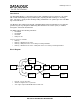
The module can be connected to an host trough a 10 wires flex cable.
The pins are used in different ways based on the fact the host is using the module to read a barcode or an
RFID tag.
In both modes the SCAN_EN signal (pin 5) can be forced low to place the module in sleep state (low-power
mode) and to switch the interface to Barcode Mode.
The module can be switched from barcode mode to RFID mode simply sending a packet on the SPI
interface.
Pins 1 and 10 are used for test and configuration at the factory and should be left unconnected.
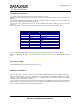
Pin # RFID Mode Barcode Mode
1 UART RX UART RX
2
VCC VCC
3
MOSI AIM
4
Clock LASER_EN
5
SCAN_EN SCAN_EN
6 /
DBP
7
MISO SOS
8
CS GND
9
GND GND
10 UART TX UART TX
Please refer to the SE950 Module integration Guide for further details about the Barcode Interface.
Please use the Datalogic RF-3 communication library software to interface to the Module when in RFID
mode.
Flex Cable Length
The maximum allowed/tested flex cable length is 75 mm.
Mechanical installation
There are two types of contrains to take into account when installing the module. The first types relate to the
Barcode reader function: to perform according to the specifications the integrated SE950 scan engine
requires a laser beam window with specific size, orientation and materials. Please refer to the SE950
intergration guide for details on this matter.
The second type of requirement is about metal parts located near the RFID antenna. Such parts could modify
the antenna resonance frequency and lead to reduced antenna effectiveness. Please keep metallic parts as
far as possible from the antenna to prevent malfunctioning.