AL5010 Product Line Manual
AccuLazr™ AL5010 Product Line Manual PN 1000068393 2.1 | CMS 11-0023 | 2013.01.31 | RAY Document Revision Control This document is under revision control in accordance with Datalogic’s Quality System. Any addenda or other documents associated with this manual are under separate revision controls. A revision number is changed by 0.1 whenever technical information is changed or added to a document. Copyright Information Copyright © 2011-2012 DATALOGIC. All rights reserved.
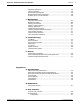
AccuLazr™ AL5010 Product Line Manuals Contents Contents Preface Intended Audience ......................................................................................... vii Thank You...................................................................................................... vii Overview of Contents.................................................................................... viii Other Sources of Information........................................................................
iv AccuLazr™ AL5010 Product Line Manuals Contents 4 Electrical Installation Prerequisites ..................................................................................................37 Tools Required.............................................................................................. 37 Additional Information ....................................................................................37 Installation Sequence(s) ......................................................................
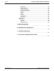
AccuLazr™ AL5010 Product Line Manuals Contents Standalone Operation ..................................................................................102 Tracking Operation ......................................................................................103 Dual X-Scanning Operation .........................................................................104 Multiple-Reader Network Operation ............................................................105 Scanning Array / Tunnel Operation ............
vi AccuLazr™ AL5010 Product Line Manuals Contents Bar Codes..............................................................................................153 Modulo Checks......................................................................................155 Stripping/Padding ..................................................................................156 Match Code Patterns.............................................................................157 Serial Communications .......................
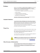
!""#$%&'()!$*+,+)-'./#"0)$123)4%2#%56! ! "#$%&'$! ! -'37%"3) *$+',-$!.,!./$!!""#$%&'()!$*+,+)-'./#"0)$123)4%2#%5!%#,-!0''123,#.! 345.$-56!78'9!:/)5!15$#!-&81&+!)8'+1;$5!./$!)8%,#-&.),8!4,1!8$$;!.,! )8.$<#&.$!$%%$'.)($+4!./$!!$*+,+)6%')7./3)83%/3'!=)./!4,1#!&>>+)'&.),89!7.! ',8.&)85!;$.&)+$;!)8%,#-&.),8!&?,1.!./$!%,++,=)8<@! !! "#,;1'.!%$&.1#$56!'&>&?)+).)$56!5>$')%)'&.),85!&8;!&''$55,#)$5! !! 3&%$.4!)8%,#-&.),8! !! 785.&++&.),8!<1);$+)8$5!&8;!>#,'$;1#$5!! !! A,8%)<1#)8>+)'&.
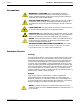
viii AccuLazr™ AL5010 Product Line Manuals Preface Conventions WARNINGS or CAUTIONS: This symbol identifies a hazard or procedure that, if incorrectly performed, could cause personal injury or result in equipment damage. It is also used to bring the user’s attention to details that are considered IMPORTANT.
AccuLazr™ AL5010 Product Line Manual Introduction 1 Introduction This chapter presents an introductory description of the AccuLazr™ AL5010 laser barcode scanner product line including: AL5010 Product Line Overview AccuLazr User Interface AL5010 Product Line Overview The AL5010 line of laser barcode readers is designed with industrial and manufacturing applications in mind, providing high-speed scanning and high reliability in a rugged industrial enclosure.
2 AccuLazr™ AL5010 Product Line Manuals Introduction AL5010 Scan Head The AL5010 Scan Head incorporates the optics and laser module(s) for scanning barcodes as well as the decoding engine and parameter storage module. The control panel provides several LED status indicators and three function buttons.
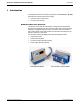
AccuLazr™ AL5010 Product Line Manual Introduction AccuLazr Interface Module The AccuLazr Interface Module is fully compatible with the AL5010 line of barcode readers and is available in both a Basic and Enhanced version.
4 AccuLazr™ AL5010 Product Line Manuals Introduction AccuLazr™ User Interface The AccuLazr User Interface lets you configure an AL5010 through a series of intuitive, user-friendly menus, tools and dialog boxes accessed via a web browser. Context sensitive help is available to assist with use of the software. With the user interface, you can: Integrate AL5010 to your system and application without custom software. Modify output messages to accommodate your system needs.
AccuLazr™ AL5010 Product Line Manual Introduction Typical AL5010 Mid-Range Barcode Reading Applications Use the AL5010 in the following applications: single-reader applications (side or top) pick module scanning multi-sided scanning retail distribution centers industrial manufacturing With optional Adjustable Raster: pallet scanning hard-to-read barcodes plastic shrink-wrapped barcodes unknown label positioning 01-AL5010_Introduction_R20.doc Accu-Sort Systems, Inc.
6 AccuLazr™ AL5010 Product Line Manuals Introduction Options and Accessories Contact your sales representative for assistance in determining which options and accessories will be applicable to your application. If you know which items are needed, contact Accu-Sort’s Customer Service Department (ask for the Spare Parts Coordinator) between 8 AM and 4:30PM (EST) Monday through Friday at 1-800-BAR-CODE (Fax: 215-7231515). Accu-Sort Systems, Inc. 01-AL5010_Introduction_R20.
AccuLazr™ AL5010 Product Line Manuals Safety 2 Safety Please follow the safety precautions and warnings found in this manual when installing, setting up, operating, maintaining, troubleshooting or replacing any Accu-Sort products, parts, or related equipment. Following these precautions will prevent personal injury or damage to the unit. Failure to follow these precautions may also void your warranty.
8 AccuLazr™ AL5010 Product Line Manuals Safety General Precautions Installation and Service by Qualified Service Technician Only WARNING: All procedures involving exposure to the inside of the AL5010 Interface Module must be performed by a trained technician because of possible exposure to emitted laser radiation, high voltage, and could reduce the effectiveness of the device’s IP rating. There are no user-serviceable parts inside.
AccuLazr™ AL5010 Product Line Manuals Safety Compliance Requirements FCC NOTICE: The AL5010 has been tested and found to comply with the limits for a Class A digital device, pursuant to Title 47, Part 15 of the FCC Rules. These limits are designed to provide a reasonable protection against harmful interference when the equipment is operated in a commercial environment.
10 AccuLazr™ AL5010 Product Line Manuals Safety Electrical Grounding Requirements Before applying power to any device, ALL components MUST be electrically grounded. Follow these precautions: Ensure all AC power outlets have a properly grounded receptacle. ALL components MUST be properly cabled and grounded with threeconductor AC power cords. Use the correct power cord for your country. Reference specific grounding instructions for each component. Do not use a two-prong adapter.
AccuLazr™ AL5010 Product Line Manuals Safety Refer to the specific ESD precautions for each component. Laser Safety The AL5010 uses visible laser diodes and emits a “moving” red beam. Do not stare into the AL5010’s exit window at the laser light source. Avoid unintentional exposure to laser light whenever possible. The laser light level does not constitute a health hazard, however staring at the laser light for prolonged periods could result in eye damage.
12 AccuLazr™ AL5010 Product Line Manuals Safety Safety Labels and Locations Refer to the following figures for specific label locations and warnings. When operating, repairing, or replacing an AL5010, note all label content on the unit. These labels provide special precautions for operation, usage specifications, product identification, and service information. WARNING: LASER LIGHT EMITTED FROM THIS APERTURE. Label Placement AL5010 Scan Head Accu-Sort Systems, Inc. 02-AL5010_Safety_R20.
$FFX/D]U $/ 3URGXFW /LQH 0DQXDOV 0HFKDQLFDO ,QVWDOODWLRQ 0HFKDQLFDO ,QVWDOODWLRQ ,03257$17 7KH $/ FRQWDLQV HOHFWURQLFV WKDW PD\ EH DIIHFWHG E\ HOHFWURVWDWLF GLVFKDUJH (6' 7R SUHYHQW SHUVRQDO LQMXU\ RU GDPDJH WR WKH XQLW SOHDVH IROORZ WKH VDIHW\ SUHFDXWLRQV DQG ZDUQLQJV IRXQG LQ &KDSWHU )DLOXUH WR IROORZ WKHVH SUHFDXWLRQV PD\ YRLG \RXU ZDUUDQW\ :$51,1* 7KHUH DUH QR XVHU VHUYLFHDEOH SDUWV LQVLGH WKH $/ 1R LQWHUQDO FRPSRQHQWV RI WKH $/ DUH ILHOG UHSODFHDEOH
14 AccuLazr™ AL5010 Product Line Manuals Mechanical Installation Unpacking Instructions IMPORTANT: The AL5010 packaging is designed to protect the unit(s) during shipment. Do not throw it away. Save all packing material in case you need to transport your unit(s). Accu-Sort Systems, Inc. 03-AL5010_Mechanical_Installation_R20.
AccuLazr™ AL5010 Product Line Manuals Mechanical Installation Installation Sequence NOTE: Everything should be MECHANICALLY INSTALLED before performing any ELECTRICAL INSTALLATION. Reference Chapter 4 for electrical installation details. Installing a Single Unit To install a single unit, follow this sequence of steps: Complete mechanical installation. Review the details of your application’s requirements. Determine and mark the reader mounting location.
16 AccuLazr™ AL5010 Product Line Manuals Mechanical Installation Orientation Considerations Consider the important factors that affect how the reader is oriented in respect to the barcoded packages (products) and their method of conveyance.
AccuLazr™ AL5010 Product Line Manuals Mechanical Installation Barcode Orientation to Scanning Area Picket Fence or Ladder Orientation Barcode placement usually determines the AL5010’s positioning. The AL5010 can be mounted to read codes in either a ladder or picket fence orientation. ← DIRECTION OF TRAVEL → Picket Fence and Ladder Orientation Illustrated Barcode Skew, Pitch and Tilt These angles affect barcode readability. Barcodes pitched or skewed up to 45 degrees are still readable.
18 AccuLazr™ AL5010 Product Line Manuals Mechanical Installation General Mounting Guidelines As you plan and install the AL5010 barcode solution for your application, be sure to keep the following mounting guidelines in mind: Determine the proper orientation and position of the reader. Leave adequate clearances for maintenance and wiring. AL5010 Reader: ~ 1-inch [25 mm] Required for scan head removal from mounting base.
AccuLazr™ AL5010 Product Line Manuals Mechanical Installation Reader Positioning: Adjustable Raster The Adjustable Raster version (sometimes referred to as “vibrating vein”) of the AL5010 uses an additional mirror that oscillates to throw the laser over a configurable area. This extra functionality has all been engineered into the original AL5010 housing. As the mirror oscillates, the scan line sweeps across the target surface in application where greater coverage is needed.
20 AccuLazr™ AL5010 Product Line Manuals Mechanical Installation Raster Setup The Adjustable Raster version of the AccuLazr™ AL5010 Laser barcode scanner requires some extra care during installation. The procedures below will help achieve the coverage needed for your application while ensuring the maximum read rate. AL5010 Adjustable Raster Installation Mount the Scanner 1. Mount the scanner according to specifications. 2. Tilt the scanner back at a 15-degree angle. 0. Set Up the Raster Sweep 1.
AccuLazr™ AL5010 Product Line Manuals Mechanical Installation 5. Position box at nearest read distance to the scanner. 6. Identify the highest and lowest code placement on the side of a box in your system. Mark the highest and lowest code positions on the test box. 03-AL5010_Mechanical_Installation_R20.doc Accu-Sort Systems, Inc.
22 Mechanical Installation AccuLazr™ AL5010 Product Line Manuals 7. In the user interface, navigate to Modify Settings > Raster. 8. Type -20 in the Upper Sweep and Lower Sweep text fields. NOTE: This will stop the raster from sweeping and lock it in position at the -20 degrees. 9. Adjust the height of the scanner, so that at -20-degrees, the scan line is aligned with the lowest barcode mark on the test box. 10.
AccuLazr™ AL5010 Product Line Manuals Mechanical Installation 13. In Modify Settings > Raster, gradually increment your upper and lower sweep values toward 0%. Try 5% increments first, i.e.: Set both the Upper Sweep and Lower Sweep to -15, then -10, -5, 0, 5, and etc. The laser should intersect a barcode at each degree setting. 14. Check the read quality on the monitor at each increment. The quality should be 100%. 15.
24 AccuLazr™ AL5010 Product Line Manuals Mechanical Installation 17. Click Update, and then click the Save icon ( ) at the top of the user interface screen. The laser will begin to sweep between your lowest and highest barcode indicators. 0. Accu-Sort Systems, Inc. 03-AL5010_Mechanical_Installation_R20.
AccuLazr™ AL5010 Product Line Manuals Mechanical Installation Run Test Labels 1. Configure the scanner for your application by setting up communications, barcode types, triggers and relays as applicable to your system (See Chapter 5 Setup). 2. In the user interface, navigate to Diagnostics > Monitor. 3. Place a test barcode at the front edge of the box in the lowest position and run the box through the system. 4. Check the Monitor screen to see how the barcode reads.
26 Mechanical Installation AccuLazr™ AL5010 Product Line Manuals 7. Continue checking for good reads by placing the label at the back edge of the box, once in the lowest position and then at the highest position. Accu-Sort Systems, Inc. 03-AL5010_Mechanical_Installation_R20.
AccuLazr™ AL5010 Product Line Manuals Mechanical Installation Dimensions and Clearances The overall dimensions of the AL5010 when the Universal Mounting Bracket (UMB) is used are shown on the mechanical specification drawings provided in the drawings folder of the documentation CD. This section also includes drawings without the UMB. The reader is a sealed, unventilated unit. No specific clearance is required for the purpose of cooling.
28 Mechanical Installation AccuLazr™ AL5010 Product Line Manuals Attaching the Universal Mounting Bracket (UMB) The Universal Mounting Bracket (UMB) is an optional accessory that simplifies reader mounting and installation. Included with the bracket is the necessary hardware to attach it to the mounting structure. 1. When using this option in your application, follow the assembly instructions provided with the universal-mounting bracket (UMB). 2.
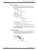
AccuLazr™ AL5010 Product Line Manuals Mechanical Installation Installing an AL5010 Scan Head Perform the electrical installation as outlined in Chapter 4. Once all wiring is checked for accuracy, install the AL5010 scan head to the mounting base. You can install the scan head with or without the power disconnected from the mounting base. To install a scan head: 1. Carefully align the scan head (1) alignment tabs to the mounting base.
30 AccuLazr™ AL5010 Product Line Manuals Mechanical Installation Mounting the Trigger Photoeye The standard photoeye works by bouncing a light beam off a reflector and detecting when something breaks the path of light. In order for photoeyes to work properly, make sure the following things are done when mounting the trigger photoeye option: Mount trigger and reflector so the reader’s scan beam does not strike either of them.
AccuLazr™ AL5010 Product Line Manuals Mechanical Installation Mounting the Tachometer The tachometer (tach) option outputs a set number of pulses for each wheel rotation. This tells the AL5010 the precise conveyor speed, allowing it to determine accurate package position. Tracking allows for multiple boxes to be in the scanning area at the same time. Barcodes on each box are decoded and assigned to the correct box.
32 AccuLazr™ AL5010 Product Line Manuals Mechanical Installation Mounting the Interface Modules Mechanical installation sequence for AL5010 with either the Basic or Enhanced Interface Module: 1. Determine the location of the scanning system at the installation site. 2. Erect the mounting frame or other supporting structures. 3. Mark the mounting locations for each: a. AL5010 Reader b. Basic or Enhanced Interface Module 4. Attach the Universal Mounting Bracket(s) (UMB) to the frame.
AccuLazr™ AL5010 Product Line Manuals Mechanical Installation To mount the Basic Interface Module: 1. Position the basic interface module in the desired mounting position. (Position the cord grips so they are face down or to the side.) 2. Using a Phillips screw driver, attach with the supplied mounting hardware. 03-AL5010_Mechanical_Installation_R20.doc Accu-Sort Systems, Inc.
34 Mechanical Installation AccuLazr™ AL5010 Product Line Manuals To mount the Enhanced Interface Module: 1. Position the basic interface module in the desired mounting position. (Position the cord grips so they are face down or to the side.) 2. Using a Phillips screw driver, attach with the supplied mounting hardware. Accu-Sort Systems, Inc. 03-AL5010_Mechanical_Installation_R20.
AccuLazr™ AL5010 Product Line Manuals Mechanical Installation Mounting the I/O Modules I/O MODULE APPLICATIONS OUTPUT MODULES Activate diverter/sorter for no read, multi-read, match, or no match conditions. Activate device (e.g., beacon light) to indicate any of the above conditions. Activate device for use as a “life condition’ indicator. Activate device to follow the trigger condition. Activate alarm.
36 AccuLazr™ AL5010 Product Line Manuals Mechanical Installation To install your optional I/O module(s): 1. Remove the cover to gain access to the printed circuit board. 2. The I/O modules may be plugged into locations I/O 1 through I/O 4. These locations run left-to-right, as shown on the circuit board silkscreen. 3. Plug the appropriate I/O module directly into the interface module’s circuit board. 4.
!""#$%&'()!$*+,+)-'./#"0)$123)4%2#%5! ! "#$%&'(%)#!*+,&)##)&(-+! ! 6!))753"0'1"%5)8290%55%01.2) :!;<8<=>!"#$%&'(%)#!*+,&)##)&(-+!./!01)#(2($3!4$'5(%$!6$%7+(%()+,! 8+#/9!0$1$')#!2'-%$34'$,!(+1-#1$!$52-,4'$!&-!1-#&)6$!(+,(3$!&7$!(+&$'8)%$! 9-34#$:!;!&')(+$3!&$%7+(%()+!94,&!2$'8-'9!&7$,$!2'-%$34'$,:!<-!+-&! )&&$92&!&-!2$'8-'9!)+=!$#$%&'(%)#!(+,&)##)&(-+!2'-%$34'$,!4+#$,,!=-4!)'$!)! &')(+$3!&$%7+(%()+:! ! :!;<8<=>!!"#$#%&$#%'(%)*#$%*#$+,-#&.
38 AccuLazr™ AL5010 Product Line Manual Electrical Installation Installation Sequence(s) NOTE: Everything should be MECHANICALLY INSTALLED before performing any ELECTRICAL INSTALLATION. See Chapter 3 for mechanical installation details. Installing a Single Unit To install a single unit, follow this sequence of steps: Complete mechanical installation. See Chapter 3. Complete electrical installation. Ground the mounting structure to protective earth (PE) ground.
AccuLazr™ AL5010 Product Line Manual Electrical Installation Installing Multiple Readers For electrical installation, multiple-reader networks will require a different approach to wiring, since the trigger photoeye and tachometer are most likely being shared by the group of readers. (See drawing 113492 in Appendix F.) Special instructions for functional set-up of a multi-reader network are provided in Chapters 5 and 6.
40 Electrical Installation AccuLazr™ AL5010 Product Line Manual Multiple Readers with a Single Interface Module General Electrical Installation Guidelines and Precautions It is important that you follow these general precautions when installing, setting up, operating, maintaining, troubleshooting or replacing any Accu-Sort products, parts or related equipment. CAUTION: The AL5010 use lasers for bar code scanning. Do not view directly with optical instruments (binoculars or telescopes).
AccuLazr™ AL5010 Product Line Manual Electrical Installation Cable and Cord Grip Connections Determine the wiring connections needed for your application. All permanent connections are made to the basic or enhanced interface module with either cables or through cord grips. Be sure to follow Accu-Sort’s wiring recommendations. Wiring Recommendations Connection Recommended Wiring Type Safety Earth Ground For 15-20 Amp branch circuit, use #18 AWG min. For 16-25 Amp branch circuit, use #14 AWG min.
42 AccuLazr™ AL5010 Product Line Manual Electrical Installation Basic Interface Module Basic Interface Module Wiring tables, printed on the interface module, help simplify installation. Basic Interface Module Terminal Block Locations See also: Drawing 113491 in Appendix F. Accu-Sort Systems, Inc. 04-AL5010_Electrical_Installation_R20.
AccuLazr™ AL5010 Product Line Manual Electrical Installation Electrical wiring sequence: 1. 2. 3. 4. 5.
44 AccuLazr™ AL5010 Product Line Manual Electrical Installation Enhanced Interface Module Enhanced Interface Module Wiring tables, printed on the interface module, help simplify installation. Enhanced Interface Module Terminal Block Locations See also: Drawing 113490 in Appendix F. Accu-Sort Systems, Inc. 04-AL5010_Electrical_Installation_R20.
AccuLazr™ AL5010 Product Line Manual Electrical Installation Electrical wiring sequence: 1. 2. 3. 4. 5. 6. 7. 8.
46 AccuLazr™ AL5010 Product Line Manual Electrical Installation Power Requirements IMPORTANT: When planning your installation wiring, remember all power connections must be quick-disconnect. For PERMANENTLY CONNECTED EQUIPMENT (i.e., AL5010 using DC power) a readily accessible disconnect device must be incorporated in the building installation wiring. For PLUGGABLE EQUIPMENT (i.e.
AccuLazr™ AL5010 Product Line Manual Electrical Installation Trigger Connections The AL5010 supports three trigger modes: hardware, software, and continuous. When using hardware trigger, one or more input signals “trigger” the reader. Software trigger is accomplished by sending a specific ASCII message via serial or network communications. Continuous trigger requires no external trigger. When a hardware trigger (i.e.
48 AccuLazr™ AL5010 Product Line Manual Electrical Installation Tachometer Connections In applications where product tracking is required, a tachometer is typically used. When a tachometer is required, the Accu-Sort tachometer is recommended. Connect the tachometer wiring to the interface module terminal blocks. Wiring Tachometer to the Enhanced Interface Module WARNING: The maximum tachometer current should not be more than 0.3 amps @ 24 volts.
AccuLazr™ AL5010 Product Line Manual Electrical Installation Serial Communications Connections (COM1 and COM2) The interface module provides an RS232/RS422 terminal block for serial point-to-point communications. Typically, network communications will use Ethernet. Enhanced Interface Module Basic Interface Module Serial Communications Wiring (RS232/422) RS232 Connections Use RS232 for a direct connection to a controller, personal computer, or other device.
50 AccuLazr™ AL5010 Product Line Manual Electrical Installation IMPORTANT: Before attempting to use RS232 communications with RTS/CTS, contact Accu-Sort Customer Service for additional information. RS422 Connections Use RS422 for a direct connection to a controller, personal computer, or other device. RS422 provides point-to-point communications at distances up to 1000 feet (300 meters). RS422 connections are made to the COM1 and COM2 terminal block.
AccuLazr™ AL5010 Product Line Manual Electrical Installation I/O Module Connections The Enhanced Interface Module supports up to four (4) optional input or output (I/O) modules. The modules listed in the table below may be used. These modules function like switches; they do not supply a voltage. (See Appendix A.) Connect I/O wiring to the correct terminal blocks. When using DC modules, observe the polarity of the connections illustrated on the circuit board.
52 AccuLazr™ AL5010 Product Line Manual Electrical Installation Output Module Application Shown below is a typical output module application. When connecting high impedance loads, you may need to add a resistor in parallel with the load. This resistor (typically 300 to 6,000 ohms) provides a continuous minimum current flow (10 mA DC or 50 mA AC) through the output module in the closed state.
AccuLazr™ AL5010 Product Line Manual Electrical Installation DeviceNet Profibus Connecting the AL5010 Once all wiring is completed and checked for accuracy, connect the AL5010 Reader’s cable connections to the Interface Module. (See Wiring the Interface Modules in this chapter.) You can install the scan head with or without the power disconnected from the interface module. (See Installing the Scan Head in Chapter 3.) 04-AL5010_Electrical_Installation_R20.doc Accu-Sort Systems, Inc.
54 AccuLazr™ AL5010 Product Line Manual Electrical Installation Wiring to the AL5010 without an Interface Module AL5010 Pin-Out Table See also: Drawing 113493 in Appendix F. Accu-Sort Systems, Inc. 04-AL5010_Electrical_Installation_R20.
AccuLazr™ AL5010 Product Line Manual Electrical Installation Check Installation After completing the installation of your AL5010: Confirm that the reader has been properly installed mechanically and electrically. Use the Installation Sequence at the beginning of this chapter and your application specifications to check your installation. Configure the reader’s parameters to meet the needs of your application. (See Chapter 5 and online help for details.
56 AccuLazr™ AL5010 Product Line Manual Electrical Installation Check installations using Enhanced Interface Module: 1. Plug in the power supply. 2. Check the following: 3. Power ‘on’ (POWER LED) Trigger photoeye operation (TRIGGER LED) Tachometer operation (TACH LED) Serial communications, receive data (RX1, RX2 LEDs) Input Relay (if applicable, I/O 1 LED). 4. Finger-tighten all water-tights. 5. Install cover. 6. Tighten four Phillips screws. Do not over tighten. Accu-Sort Systems, Inc.
AccuLazr™ AL5010 Product Line Manual Setup 5 Setup Getting Started The AL5010 line of laser bar code readers is designed for ease-of-setup, allowing you to program a reader to fit your application seamlessly. AccuLazr™ User Interface for AL5010 is a browser-based application. It is the tool you will use to define operating parameters, determine bar code read quality, and construct output messages, including filtering, stripping and padding capabilities.
58 Setup AccuLazr™ AL5010 Product Line Manual Starting the AccuLazr User Interface To start the AccuLazr™ User Interface software in the Windows environment: 1. Open your web browser and enter the IP address for your AL5010 unit. If the correct IP address is entered, the AL5010 Login screen will appear (If you don’t know the IP address, see Discovering the IP Address in Chapter 8.) The default IP address is: 192.168.3.100 2. Enter the User ID and Password for your system in the fields provided. 3.
AccuLazr™ AL5010 Product Line Manual Setup AccuLazr User Interface Basics AccuLazr™ User Interface Menu Tree The functions that you can select are displayed in a navigation list on the left–hand side of the AccuLazr™ User Interface. The function list is organized much like the hierarchy of a file system, where you can expand items that begin with a plus sign (+) to further sub–levels until you find a function of interest. Sub–levels appear indented below the items from which they are expanded.
60 AccuLazr™ AL5010 Product Line Manual Setup Modify Settings Use the Modify Settings menu tree selections during initial setup to configure your AL5010 Laser Bar Code Reader. If necessary, you can later make modifications to the reader’s configuration using the same menu selections, including: Accu-Sort Systems, Inc.
AccuLazr™ AL5010 Product Line Manual Setup Modify Settings > Configuration Use Configuration to identify and configure an AL5010 bar code reader. This includes access to reader information as well as configuration options (scan rate, control panel and network access). To set the reader Configuration: 1. Click in the Reader Name entry field and enter a unique reader name up to 15-characters in length. Use of unique reader names is especially useful in multiple scanner applications. 2.
62 AccuLazr™ AL5010 Product Line Manual Setup Modify Settings > Bar Codes Use Bar Codes to define the symbologies the AL5010 should read for your application. Modulo check verification within a bar code can also be specified. Create bar code groups, if needed. Bar Code Groups When more than one bar code type is in the Selected Symbologies list, the Bar Code Groups tab is available. This enables you to define the valid “groups” of bar codes that are to be transmitted together.
AccuLazr™ AL5010 Product Line Manual Setup To add a bar code manually: 1. To add a bar code, go to the Modify Settings > Bar Code screen. 2. Be sure you know the parameters for the symbology you are adding to your active list. 3. Select the symbology from the Code Type drop-down list. 4. Assign a unique Code Label, if necessary. 5. Define the minimum and maximum code length. 6. Define the minimum and maximum quantity. 7. Select the Modulo Check. 8. Enter a Filter, if required. 9. Click Add.
64 AccuLazr™ AL5010 Product Line Manual Setup To create a bar code group: 1. Go to the Bar Code Groups tab. (This tab becomes available when two or more codes are available under Selected Symbologies.) 2. Create Group 1 by clicking the checkbox for the codes to be included in the group. 3. Create any additional groups required. 4. Click Update. 0. See also: Modify Settings > Bar Codes in Appendix C. Accu-Sort Systems, Inc. 05-AL5010_Setup_R20.
AccuLazr™ AL5010 Product Line Manual Setup Modify Settings > Modulo Checks Use the Modulo Checks screen to setup the user defined modulo checks for any bar code symbologies that you have specified need them. If you selected a User Defined Modulo Check while in the Modify Settings > Bar Codes setup screen, you will need to define it on the Modulo Checks screen.
66 AccuLazr™ AL5010 Product Line Manual Setup Modify Settings > Stripping/Padding For each symbology type (defined in Modify Settings > Bar Codes), stripping and/or padding of the bar code data can be specified. This stripping and padding is applied to the bar code before any message formatting. NOTE: Character stripping is applied before character padding. To set the character stripping for a bar code: 1. Select the bar code from the Available Bar Codes drop-down list. 2.
AccuLazr™ AL5010 Product Line Manual Setup Modify Settings > Match Codes Use Modify Settings > Match Codes to define a specific code pattern within a symbology type that is to be considered a "match condition". In addition to identifying and reading a symbology you defined (using Modify Settings > Bar Codes), this feature enables you to configure a reader to match specific select characters within a bar code. All bar codes are compared to the complete list of Match Codes.
68 AccuLazr™ AL5010 Product Line Manual Setup Modify Settings > Serial Communications Use the Serial Communications menu tree selections to set the serial port connection parameters including: • Baud Rate • Data Bits • Stop Bits • Parity • Flow Control • Message Format Individual settings can be made for Serial Port 1 and Serial Port 2. If the User Defined Message format is selected, an addition tab screen is supplied for creating unique message definitions.
AccuLazr™ AL5010 Product Line Manual Setup To create user-defined messages: Under Message Format, select User Defined Message. A Message Definitions tab becomes available. For the serial port, select Message Definitions – Port #1(or 2) (example shown below). For network communications, select Message Definitions – Net#1(or 2). To define message framing: Header - Character string specified for the header. Sent at beginning of every message. Trailer - Character string specified for the trailer.
70 Setup AccuLazr™ AL5010 Product Line Manual Multiple Bar Code - If disabled, a multiple bar code condition will be reported as a “Read” of the first bar code reported. Otherwise, the specified “repeated character” or the user-specified message is sent. Category 2: Match, No Match, No Match Read These conditions are IN ADDITION to the conditions specified in Category 1. If a condition in both categories is met, these messages will be appended.
AccuLazr™ AL5010 Product Line Manual Setup Modify Settings > Network Use Modify Settings > Network to specify network settings (including the IP address) for the reader. Currently, the reader can only be configured to use a Static IP address. Net Host Port1 and Net Host Port2 define two network connections for sending bar code messages. The Connection Type and Message Format for each port can be set independently. Message formatting is the same as for the serial port.
72 AccuLazr™ AL5010 Product Line Manual Setup Ethernet Link Drop-down list with 5 selections: AutoDetect, 100 Mbps/Full Duplex, 100 Mbps/Half Duplex, 10 Mbps/Full Duplex, 10 Mbps/Half Duplex • Controller Multicast IP Address: This is the IP address used by this controller to communicate to its Group (Identified by the Group No.) to broadcast such messages as tach and trigger. NOTE: • This IP address should not be changed. Telnet Port: The port number used to Telnet into the AL5010.
AccuLazr™ AL5010 Product Line Manual Setup To define Serial Port 1 message content: The message drop-down lists define the message options for each bar code. The message content can be defined for transmissions from the reader’s serial port #1 as well as any network connection (via Net#1). These messages are based on various conditions. For each condition, there are options for what message can be sent. These options include: Send Bar Code - Bar code (with padding and/or stripping) is sent.
74 AccuLazr™ AL5010 Product Line Manual Setup Modify Settings > Trigger The trigger helps the reader identify when products with bar codes are entering the scanning area. Use Modify Settings > Trigger Settings to set the various trigger parameters.
AccuLazr™ AL5010 Product Line Manual Setup Modify Settings > Relay Use to define functionality of any I/O relay module options utilized by your reader. For additional information and field descriptions, see Modify Settings > Relay in Appendix C. To configure an I/O relay: 1. Select the intended use of the relay (output or input). 2. Select the intended purpose for the relay. 3. Set for either Active High or Active Low. 4. For relay outputs, set an output signal duration. 5.
76 AccuLazr™ AL5010 Product Line Manual Setup Modify Settings > Tracking Use tracking in application that require: • Tight package spacing • Transmit point is greater than the "smallest box + minimum box spacing" distance. Use Modify Settings > Tracking to define all of the parameters associated with monitoring package travel on the conveyance system. The tracking parameters are only available if tracking is enabled, otherwise they are not shown in this window. To enable tracking: 1.
AccuLazr™ AL5010 Product Line Manual Setup Modify Settings > FAST Monitor™ FAST Monitor is a browser-based application, running on a FAST Monitor Server, that gives facility managers and maintenance personnel the ability to monitor multiple Accu-Sort products within their facility or across multiple facilities from anywhere an internet connection is available.
78 AccuLazr™ AL5010 Product Line Manual Setup Modify Settings > Advanced The Advanced screen provides filters for enhancing the scanners ability to read a bar code. Adjusting these values may have a negative or positive effect on the reader’s ability to decode a bar code. The Data Filtering, DRX (Data Reconstruction) and Transmit QQ settings are considered advanced settings because they require comprehensive training to understand how they should be modified.
AccuLazr™ AL5010 Product Line Manual Setup • Should be at least as long as Start/Stop character. If short Start/Stop character, use the length of one data character plus the start/stop character (e.g.;I2 of 5) • In this subroutine, any group of elements less than the min trans setting is discarded or ignored. Laser /Laser 2 DOF: Near Dist (in)/Far Dist (in) • These options filter out any transitions beyond the entered values.
80 AccuLazr™ AL5010 Product Line Manual Setup Modify Settings > Raster Use Modify Settings > Raster to define the laser sweep area of an AL5010 with the optional adjustable raster feature. It also allows you to set the oscillating frequency (speed) of the vibrating mirror. The sweep of the laser is determined by the amount of coverage your application requires (possible label position) and the distance of the laser scanner from the object being scanned.
AccuLazr™ AL5010 Product Line Manual Setup Save / Retrieve Use Save/Retrieve to save all the settings to the scan head and backup the settings to the mounting base and/or file. To use the save/retrieve functions: 1. Select an Action. Based on the action selected, either the From or To drop-down list becomes available. 2. Select the required location (either From or To). 3. Follow any additional prompts. For example: If Retrieve from File is selected, use the Browse function provided to locate the file. 4.
82 AccuLazr™ AL5010 Product Line Manual Setup Diagnostics The AL5010 includes comprehensive diagnostic that enable you to monitor: Accu-Sort Systems, Inc. • Status LEDs • Read Quality • Messages • Box Information • Message Monitor • Read Rate Log • Counters Log • Message Log • Upload Firmware 05-AL5010_Setup_R20.
AccuLazr™ AL5010 Product Line Manual Setup Diagnostics > Monitor Use the Diagnostics > Monitor as the primary tool to monitor the reader's operation and bar code readability in real-time. Status indicators and vital statistics appear on a single screen, enabling you to effectively and efficiently detect and troubleshoot any problems that may occur. The Monitor is a Java application and requires Java and the appropriate browser plug-in. See also: Diagnostics > Monitor in Appendix C. 05-AL5010_Setup_R20.
84 AccuLazr™ AL5010 Product Line Manual Setup Diagnostics > Log Viewer The Diagnostics > Log Viewer lets you review the performance logs saved by the reader. The three most commonly viewed logs are available by selecting one of the three buttons: • Read Rate • System Counters • Message Log You can also enter a log request in the Command field. For example: DISPENET will provide Ethernet data. The log view field remains empty until you select a button or enter a command.
AccuLazr™ AL5010 Product Line Manual Setup Read Rate Counters by Laser The Read Rate Log Viewer also provides performance information on each laser. In order to provide diagnostics on the performance of each laser, the percentage references here are the percentage of the total codes read by the particular laser, NOT the percentage of the total packages read by that laser. Total Codes Total number of bar codes read.
86 AccuLazr™ AL5010 Product Line Manual Setup Counters Log View Use the Counters Log View to display a number of values and counters that indicate whether the reader is configured and operating properly. To open the System Counters Log View: 1. Click Counters, or 2. Enter DISPCOUNTS in the command field. Click Send Command. 3. The system counters log is shown in the viewer. 4. Click Clear to empty the viewer and display another log. 0.
AccuLazr™ AL5010 Product Line Manual Setup Error Counters 05-AL5010_Setup_R20.doc Xfter Ovrflw Transfer Overflow. This counts the number of codes that were lost due to an overflow in the transfer buffer between the Decode/DSP processor and the reader/ARM processor. Xfer BadLen Transfer Bad Length. Number of codes in the transfer buffer than contained an invalid length, indicating some sort of memory corruption. QData@TX Queue Data at Transmit (non-tracking).
88 AccuLazr™ AL5010 Product Line Manual Setup Decode/DSP Counters DSP Codes Count of the number of bar codes decoded, per laser, by the DSP. Scan Ints Number of scan interrupts detected by the DSP. Queue Size Current size of the scan data queue within the DSP. This value changes dynamically. Num Cluster Current number of DRX clusters in use by the DSP. This value changes dynamically. Bad Scan Count of the number of scans in which the data contained formatting errors.
AccuLazr™ AL5010 Product Line Manual Setup Command There are several commands that you can use to display reader parameters and diagnostic information. Commands can be sent from the Command field on the Log Viewer. Commands may also be sent from a terminal interface, such as a TELNET connection to the reader. 05-AL5010_Setup_R20.doc Log Viewer Commands Definition CLEAR ALL Clears all information from the Message Monitor. DISP COUNTERS Display the System Counter log view.
90 AccuLazr™ AL5010 Product Line Manual Setup Diagnostics > Update Firmware Use Diagnostics > Update Firmware to reload the reader firmware. For additional information and field descriptions, see Diagnostics > Update Firmware in Appendix C. CAUTION: This function should only be performed under the guidance of Accu-Sort Technical Support. To Extract Image 1. Click Extract Image. 2. In Save as window, save the image (*.as) files to your computer.
AccuLazr™ AL5010 Product Line Manual Operations 6 Operations This chapter provides details on how the AL5010 bar code scanning solutions function during normal operation.
92 AccuLazr™ AL5010 Product Line Manual Operations First-time Setup Every application is unique. AL5010 is designed for ease-of-setup, allowing you to program the reader to fit your application seamlessly. A browser-based setup application on your laptop/desktop computer is the tool you will use to define operating parameters, set bar code type / length, and construct output messages, including filtering, stripping and padding capabilities.
AccuLazr™ AL5010 Product Line Manual Operations 7. Run the browser-based setup application and establish a connection with the reader. 8. Go to the Diagnostics > AL5010 Monitor. 9. During operations, use the AL5010 Monitor to confirm the reader’s status, read quality, code quality, and messages via the on-screen indicators. (See Chapter 8, Diagnostics.) 10. Close the connection to the reader. 11. Disconnect setup cable. Operations Checklist 06-AL5010_Operations_R20.
94 Operations AccuLazr™ AL5010 Product Line Manual Control Panel Indicators There are several control panel indications on the AccuLazr AL5010 Readers and AccuLazr Interface Modules. Accu-Sort Systems, Inc. 06-AL5010_Operations_R20.
AccuLazr™ AL5010 Product Line Manual Operations The LEDs provide the following indications during normal operations. Using LED Indicators to Check Normal Operations 06-AL5010_Operations_R20.doc LED Description STATUS GREEN to indicate the overall "health" of the reader. (If RED, see Chapter 8, Troubleshooting.) TRIGGER Indicates the trigger input. The LED is activated upon trigger input regardless of trigger source (incl. software trigger).
96 AccuLazr™ AL5010 Product Line Manual Operations NETWORK LED during Normal Operations Mode Single TCP/IP Description Solid GREEN – AL5010 connected to a host. NOTE: If both Host 1 and Host 2 are used, the LED will be solid GREEN if either port is connected. Off – No host connection. NOTE: If UDP messaging is used (unconnected messages) the Network LED will be off.
AccuLazr™ AL5010 Product Line Manual Operations Interface Module Status Indicators LEDs on Basic Interface Module LEDs on Enhanced Interface Modules 06-AL5010_Operations_R20.doc Accu-Sort Systems, Inc.
98 AccuLazr™ AL5010 Product Line Manual Operations FieldBus LED Status Indicators DEVICENET Module Status FB1 FB1 FB2 FB2 Network Status FB3 FB3 FB4 FB4 Off - No power Green Normal operation Green, flashing Auto Baud in progress Red Unrecoverable Fault(s) detected Red, flashing Recoverable Fault(s) detected Alternating Red/Green Self test in progress Off - Not online - or - no power Green On-line, one or more connections established Green, flashing On-line, no connections established Red Critical link f
AccuLazr™ AL5010 Product Line Manual Operations Backup / Restore Procedures To backup parameters from scan head to mounting base: 1. Press the backup button for about 1 second. 2. Release button. The bar graph LEDs continuously flash to indicate the button has been pressed long enough. If the LEDs flash only once, the button was not pressed long enough. 3. Press button a second time while LEDs are flashing. Hold for about 1 second. 4. Release button.
100 Operations AccuLazr™ AL5010 Product Line Manual Checking Operations with User Interface The Diagnostics > Monitor enables you to evaluate the operational performance of your AL5010 by providing vital statistics via status indicators, real-time read quality monitoring, and box information. Outgoing and incoming messages are also monitored. Diagnostics > Monitor Window Accu-Sort Systems, Inc. 06-AL5010_Operations_R20.
AccuLazr™ AL5010 Product Line Manual Operations Checking Multi-Reader Network From the AL5010 Controller, check Diagnostics > Log Viewer > Read Rate. This simple diagnostic allows you to check bar codes read, by laser, for each AL5010 Client in the network. Each client is identified in the Read Rate Log by the unique name and IP address assigned to it. See Chapter 5 and online help for more information. 06-AL5010_Operations_R20.doc Accu-Sort Systems, Inc.
102 AccuLazr™ AL5010 Product Line Manual Operations Standalone Operation In a typical standalone setup, a single AL5010 scans bar codes on one side of packages as they move down a conveyor. A photoeye is used to trigger the AL5010 to begin searching for valid bar codes. Bar code data is transmitted to a host device. Typical Single-Unit AL5010 Applications Accu-Sort Systems, Inc. 06-AL5010_Operations_R20.
AccuLazr™ AL5010 Product Line Manual Operations Tracking Operation By utilizing the tracking capabilities of the AL5010, you can configure your application to monitor the progress of packages on the conveyance system. Tracking enables the AL5010 to track bar codes and the packages to which they belong. Your reader may scan more than one package with more than one code at a time within its read zone. Tracking allows the reader to accurately associate the correct bar code(s) with the correct packages.
104 AccuLazr™ AL5010 Product Line Manual Operations Dual X-Scanning Operation In dual X-scanning applications, four AL5010 readers mounted side-by-side are used to create a dual “X” scanning patterns across the entire width of a conveyor. Four UMB brackets and four AL5010 readers can be used to create a dual-X scanning pattern.
AccuLazr™ AL5010 Product Line Manual Operations Multiple-Reader Network Operation In multiple-reader applications, from 2 to 14 AL5010s can be networked together. A single AL5010 is configured as a Controller for a multiple-reader network. The AL5010 Controller gathers data from other AL5010s (up to 13, configured as clients) over an Ethernet network. The AL5010 Controller then collects and transfers the collected data over a serial communications or network link to the host.
106 AccuLazr™ AL5010 Product Line Manual Operations Scanning Array / Tunnel Operations The AL5010 can be set up with 1 controller and up to 13 clients in a single system and functioning in the same scanning area, the entire application is called a scanning array or tunnel. NOTICE: Due to the complexity of these applications, tunnel arrays are typically custom-engineered to your specifications.
AccuLazr™ AL5010 Product Line Manual Maintenance 7 Maintenance This chapter provides instructions for maintaining optimum performance and life for your AL5010.
108 Maintenance AccuLazr™ AL5010 Product Line Manual Maintenance Tasks Perform the maintenance tasks on an “as needed” basis to assure proper operation of the AL5010. Task schedule frequency depends upon the application environment conditions. It only requires a few minutes to complete each maintenance task. Exterior Cleaning WARNING: Shut down the reader before performing this maintenance task. Do not stare into the reader’s exit window at the laser light. Avoid direct eye exposure.
AccuLazr™ AL5010 Product Line Manual Maintenance Cleaning the Exit Window WARNING: Shut down the reader before performing this maintenance task. Do not stare into the reader’s exit window at the laser light. Avoid direct eye exposure. The laser light level does not constitute a health hazard, however staring at the laser light for prolonged periods could result in eye damage. WARNING: There are no user serviceable parts inside the AL5010.
110 Maintenance AccuLazr™ AL5010 Product Line Manual Cleaning the Trigger Photoeye If your application uses the photoeye option as a hardware trigger, be sure to clean the photoeye periodically as outlined below. 1. Turn off the product transport. 2. Turn off the reader’s lasers. 3. Clean the photoeye’s lens using the denatured alcohol solution and a cotton swab or lens paper. Check the reflector on the opposite side of the transport. Clean as necessary. 4. Verify photoeye operation.
AccuLazr™ AL5010 Product Line Manual Maintenance Cleaning the Tachometer If your application uses the tachometer option for tracking purposes, be sure to clean the tachometer wheels periodically as outlined below. 1. Turn off the product transport. 2. Turn off the reader’s lasers. 3. Using a clean, soft cloth, wipe the wheels of the tachometer clean using a mild detergent solution. 4. Before restarting the system, be sure the tachometer is making good contact with the product transport. 5.
112 Maintenance AccuLazr™ AL5010 Product Line Manual Verify Reader Operation Follow the Operations Checklist procedure defined in Chapter 5. If the reader parameters were changed to read bar codes other than the factory defaults, simply use a good quality bar code to assist in verifying proper operations. There is no need to return the reader to the default parameters to perform this test. Verify Photoeye Operation 1. Block the photoeye beam to confirm it is aligned properly with the reflector. 2.
AccuLazr™ AL5010 Product Line Manual Troubleshooting 8 Troubleshooting This chapter provides instructions for diagnosing, troubleshooting and correcting AccuLazr AL5010 performance issues. It provides specific information on: Test Mode Indicators Diagnostics Troubleshooting (Problem/Cause/Solution) Test Mode In test mode, the AL5010 displays the read rate on the AL5010 control panel’s bar graph LEDs.
114 AccuLazr™ AL5010 Product Line Manual Troubleshooting Control Panel Indicators There are several control panel indications on the AccuLazr AL5010 Readers and AL5010 Interface Module. AL5010 Reader Control Panel Basic Interface Module Enhanced Interface Module AL5010 Interface Module Status Indicator LEDs Accu-Sort Systems, Inc. 08-AL5010_Troubleshooting_R20.
AccuLazr™ AL5010 Product Line Manual Troubleshooting Control Panel LED Fault Detect Descriptions LED Description STATUS RED indicates a problem regarding the overall "health" of the reader. TRIGGER Indicates the trigger input. The LED is controlled through software no matter the trigger source (including software trigger). READ RED identifies a No Read condition. Check bar code print quality, trigger configuration, and bar code parameters.
116 AccuLazr™ AL5010 Product Line Manual Troubleshooting NETWORK LED – Fault Detection Only Mode Single TCP/IP Description LED is Off – No host connection or UDP messaging is used. NOTE: If UDP messaging is used (unconnected messages) the Network LED will be off.
AccuLazr™ AL5010 Product Line Manual Troubleshooting Diagnostics The AccuLazr User Interface includes comprehensive diagnostic capabilities that monitor reader operation, triggering, conveyor speed, package and label dimensions, bar code readability, scan rates and message output. The Diagnostics > Monitor window is the primary tool used to monitor the reader's operation and bar code readability in real-time. The Diagnostics > Log Viewer lets you review the performance logs saved by the AL5010.
118 AccuLazr™ AL5010 Product Line Manual Troubleshooting Status LEDs The Monitor status indicators reflect the AL5010 control panel LEDs functionality as well as additional LEDs such as the Match and I/O LEDs. Status LED Definitions LED Conditions Status Green Red Trigger Green Definition of Conditions Indicates the overall “health” of the reader. Fault condition: Troubleshooting is required. Indicates the trigger input.
AccuLazr™ AL5010 Product Line Manual Troubleshooting Read Quality The Read Quality indicators provide information regarding the bar code that was read. Read Quality Definitions Read Quality Graph 0-100 Scans/Code Code Position (slider) Code Quality (QQ) Laser 1 through 4 Definition The large percentage bar maps to the values displayed on the reader bargraph. It is a measure of “how well” the bar code was read. Indicates how many passes of the laser (scan lines) contributed to the reading of the code.
120 AccuLazr™ AL5010 Product Line Manual Troubleshooting Log Viewer The Diagnostics > Log Viewer lets you review the performance logs saved by the AL5010. The log view field remains empty until you select one of the three most common logs (Read Rate, System Counters, or Message Log) via the buttons or enter a log request in the Command field. Log Viewer Commands There are several commands that you can use to display AL5010 parameters and diagnostic information.
AccuLazr™ AL5010 Product Line Manual Troubleshooting Read Rate Log View For a summary of the AL5010’s overall performance, click the Read Rate button. You can also enter DISPREADRATE in the command field and click Send. Diagnostics > Log Viewer (Read Rate selected) The Read Rate Log Viewer provides information on the overall read rate. Overall Read Rate Counters Read Rate Total Boxes Good Boxes Partial Boxes Bad Boxes 08-AL5010_Troubleshooting_R20.doc Description Total number of triggers.
122 AccuLazr™ AL5010 Product Line Manual Troubleshooting The Read Rate Log Viewer also provides performance information on each laser. In order to provide diagnostics on the performance of each laser, the percentages reference here are the percentage of the total codes read by the particular laser, NOT the percentage of the total packages read by that laser. Read Rate Counters per Laser Read Rate Total Codes Laser#x Description Total number of bar codes read.
AccuLazr™ AL5010 Product Line Manual Troubleshooting System Counters Log View You can display a number of values and counters that indicate whether the AL5010 is configured and operating properly by clicking the System Counters button. You can also enter DISPCOUNTERS in the command field and click Send. Scan Rate and Belt Speed System Counters Scan Rate Belt Speed Description This is the total number of scans/second that the AL5010 is reading.
124 AccuLazr™ AL5010 Product Line Manual Troubleshooting ForcedTx Lost Codes Missed Tx Forced Transmit (non-tracking). A forced transmit indicates that the start of trigger occurred before the specified transmit delay time had expired. Lost Codes (tracking). If a bar code cannot be placed onto any package while in tracking, the code is “lost” and this counter is incremented. Lost codes are also reported in the AL5010 Monitor message window.
AccuLazr™ AL5010 Product Line Manual Troubleshooting Message Log View The Message Log contains various text messages that have been logged by the AL5010 software. You can view these messages by clicking the Message Log button. You can also enter DISPMSGLOG in the command field and click Send. The messages contained in this log typically reflect significant events. Update Firmware CAUTION: Used to reload AL5010 reader firmware.
126 AccuLazr™ AL5010 Product Line Manual Troubleshooting Troubleshooting The following PCS (problem/cause/solution) tables are designed to assist you in troubleshooting the more common events that may occur during installation and operation of your AccuLazr AL5010. PCS Troubleshooting Problem Cause(s) Solution(s) Problem Cause(s) Solution(s) Problem Cause(s) Solution(s) Accu-Sort Systems, Inc. The POLARITY LED in the wiring base is RED.
AccuLazr™ AL5010 Product Line Manual Troubleshooting PCS Troubleshooting (continued) Problem Cause(s) Solution(s) Problem Cause(s) Solution(s) The AL5010 is experiencing poor read rate in hardware trigger. Photoeye is not adjusted properly or requires alignment. 1. Verify that the photoeye is blocked the entire time the reader’s laser is scanning the bar code. 2. Adjust the photoeye as necessary. (See Verify Photoeye Operation in Chapter 7.) NOTE: For non-tracking applications only.
128 Troubleshooting AccuLazr™ AL5010 Product Line Manual Discovering the IP Address If you don’t know the IP address for the AL5010 unit, it can be found in two ways. To Discover the IP Address Using Recovery Mode: 1. Unplug the power to the AL5010 system. 2. Hold down the “!” button on the back of the reader while you restore power. 3. Release the button. The LEDs should strobe from 5 to 1 and the status LED will be RED indicating that the unit is in Recovery Mode. 4. Open a browser and type 192.168.3.
!!"#$%&'( #)*+*(,&-."!/(#012(3$1"$4 !"#$%&" !!52&60!2( *+"#" ,#" , -%.%/"0 12.3"# 45 5%"-06#"7-,&",3-" 21%/8 9:;<8= /+,/ ,#" 7,#/ 45 /+" >?@A'AB C1 .48/ &,8"8D &4.741"1/8 8+42-0 3" #"7-,&"0 E%/+ , .,/&+%1F #"&4.."10"0 87,#" 7,#/ 9;!G=B !"#$%&" 7#4&"02#"8 ,#" 0%$%0"0 %1/4 /E4 8H%-- -"$"-8I J28/4."# /"&+1%&%,18 9E%/+ 84." /#,%1%1F 5#4. >&&26!4#/= >&&26!4#/ *#,%1"0 ,10 >2/+4#%K"0 !"#$%&" *"&+1%&%,18 41-L >-- >?@A'A ,&&"884#%"8 ,10 47/%418 ,#" &418%0"#"0 &28/4.
130 AccuLazr™ AL5010 Product Line Manual Service FRU Guide Spare Part Number Replacement Assembly Descriptions 1000067750 Scan Head (1L-SD) 1-laser, standard density 1000067751 Scan Head (1L-HD) 1-laser, high density 1000067752 Scan Head (1L-NHD) 1-laser, near focus, high density 1000067753 Scan Head (2L-SD) 2-laser, standard density 1000067754 Scan Head (2L-HD) 2-laser, high density AL5010 Bar Code Reader 1000070389 NOTE: For Adjustable Raster versions or units with custom s
AccuLazr™ AL5010 Product Line Manual Service FRU Guide Spare Part Number Replacement Assembly Descriptions AL5010 Interface Module 1000070391 0111631001 Basic Interface Module Trig, Ethernet, (1) serial port (RS232/422 selectable) 1000070384 0111633001 Enhanced Interface Module with DeviceNet Tach, Trig, Ethernet, (2) serial port (RS232/422 selectable), (4) I/O 0111633002 Enhanced Interface Module with DeviceNet Tach, Trig, Ethernet, (2) serial port (RS232/422 selectable), (4) I/O
132 Service AccuLazr™ AL5010 Product Line Manual Notes: Accu-Sort Systems, Inc. 09-AV5010_Service_R20.
AccuLazr™ AL5010 Product Line Manual Appendix A: Specifications Specifications AccuLazr™ AL5010 Technical Specifications Characteristic Name (1) Scan Head* 1 Laser, Standard Density 1 Laser, High Density 1L, High Density, Near Focus 2L, Low Density, High Pitch 2 Laser, High Density Optional Adjustable Raster (2) Mounting Base/Cable Size Weight Enclosure Temperature Relative Humidity Laser Type Power Requirement Power Consumption Visual Indicators (LEDs) Bar Code Types Connectors (Mounting Base) Communica
134 AccuLazr™ AL5010 Product Line Manual Appendix A: Specifications AccuLazr™ Basic Interface Module Technical Specifications Characteristic Name Size Weight Description AccuLazr™ Basic Interface Module (0111631001) H 92.5 mm [3.64”] x W 136.4 mm [5.37”] x D 65.0 mm [2.56”] Basic Interface Module: 0.317 kg [0.7 lbs] Power Supply: 0.498 kg [1.
AccuLazr™ AL5010 Product Line Manual Appendix A: Specifications Power Supply for AL5010 Characteristic Dimensions Weight Temperature Relative Humidity Enclosure Power Requirements Power Consumption Connections Compliance Description L 4.65” [118 mm] x W 1.36” [34.5 mm] x H 2.05” [52 mm] 0.6 lbs. [0.275 kg] Operating: 0° to +70° C Storage: -40° to +85° C 5-95% non-condensing ABS plastic, Rated for IP40 Input: 90-264 VAC / 0.5A typical, 1.0A max. @ 120 VAC Output: Max.
136 AccuLazr™ AL5010 Product Line Manual Appendix A: Specifications Certifications UL Listing UL Listed UL Listed to Canadian safety standards Standard to which conformity is declared: EN60950: Test Spec: IEC 60950 3RD Edition / (2000) (Information Technology Equipment (I.T.E.
AccuLazr™ AL5010 Product Line Manual Appendix B: Read Charts Read Charts How to identify the scan head model: The model type is shown on the serial label. 1L – Indicates a scan head that is using one laser. 2L – Indicates a scan head that is using two lasers. SD – Identifies a standard density scan head for reading bar codes with minimum bar/space widths of 15 mil+. HD – Identifies a high density scan head for reading bar codes with minimum bar/space widths of 10 mil+.
138 AccuLazr™ AL5010 Product Line Manual Appendix B: Read Charts Combo Read Chart / Table 1,200 scans per second (standard) throughout DOF ANSI Contrast Grade 84% or greater ANSI “Grade A” Print Quality Accu-Sort Systems, Inc. Pitch not greater than +/- 15 ° Skew not greater than +/- 15 ° Tilt not greater than +/- 45 ° A2-AL5010_Read_Charts_R20.
AccuLazr™ AL5010 Product Line Manual Appendix B: Read Charts AL5010-1L NHD: 1 Laser, Near Focus High-Density Scan Head Part Number 1000067752 10 mil code 1,200 scans per second (standard) throughout DOF ANSI Contrast Grade 84% or greater ANSI “Grade A” Print Quality A2-AL5010_Read_Charts_R20.doc Pitch not greater than +/- 15 ° Skew not greater than +/- 15 ° Tilt not greater than +/- 45 ° Accu-Sort Systems, Inc.
140 AccuLazr™ AL5010 Product Line Manual Appendix B: Read Charts AL5010-1L HD: 1 Laser, High-Density Scan Head Part Number 1000067751 10 mil code 1,200 scans per second (standard) throughout DOF ANSI Contrast Grade 84% or greater ANSI “Grade A” Print Quality Accu-Sort Systems, Inc. Pitch not greater than +/- 15 ° Skew not greater than +/- 15 ° Tilt not greater than +/- 45 ° A2-AL5010_Read_Charts_R20.
AccuLazr™ AL5010 Product Line Manual Appendix B: Read Charts AL5010-1L HD: 1 Laser, High-Density Scan Head Part Number 1000067751 14 mil code 1,200 scans per second (standard) throughout DOF ANSI Contrast Grade 84% or greater ANSI “Grade A” Print Quality A2-AL5010_Read_Charts_R20.doc Pitch not greater than +/- 15 ° Skew not greater than +/- 15 ° Tilt not greater than +/- 45 ° Accu-Sort Systems, Inc.
142 AccuLazr™ AL5010 Product Line Manual Appendix B: Read Charts AL5010-1L HD: 1 Laser, High-Density Scan Head Part Number 1000067751 20 mil code 1,200 scans per second (standard) throughout DOF ANSI Contrast Grade 84% or greater ANSI “Grade A” Print Quality Accu-Sort Systems, Inc. Pitch not greater than +/- 15 ° Skew not greater than +/- 15 ° Tilt not greater than +/- 45 ° A2-AL5010_Read_Charts_R20.
AccuLazr™ AL5010 Product Line Manual Appendix B: Read Charts AL5010-1L SD: 1 Laser, Standard Density Scan Head Part Number 1000067750 15 mil code 1,200 scans per second (standard) throughout DOF ANSI Contrast Grade 84% or greater ANSI “Grade A” Print Quality A2-AL5010_Read_Charts_R20.doc Pitch not greater than +/- 15 ° Skew not greater than +/- 15 ° Tilt not greater than +/- 45 ° Accu-Sort Systems, Inc.
144 AccuLazr™ AL5010 Product Line Manual Appendix B: Read Charts AL5010-1L SD: 1 Laser, Standard Density Scan Head Part Number 1000067750 20 mil code 1,200 scans per second (standard) throughout DOF ANSI Contrast Grade 84% or greater ANSI “Grade A” Print Quality Accu-Sort Systems, Inc. Pitch not greater than +/- 15 ° Skew not greater than +/- 15 ° Tilt not greater than +/- 45 ° A2-AL5010_Read_Charts_R20.
AccuLazr™ AL5010 Product Line Manual Appendix B: Read Charts AL5010-2L HD: 2 Lasers, High Density Scan Head Part Number 1000067754 10 mil code 1,200 scans per second (standard) throughout DOF ANSI Contrast Grade 84% or greater ANSI “Grade A” Print Quality A2-AL5010_Read_Charts_R20.doc Pitch not greater than +/- 15 ° Skew not greater than +/- 15 ° Tilt not greater than +/- 45 ° Accu-Sort Systems, Inc.
146 AccuLazr™ AL5010 Product Line Manual Appendix B: Read Charts AL5010-2L SD: 2 Lasers, Standard Density Scan Head Part Number 1000067753 15 mil code 1,200 scans per second (standard) throughout DOF ANSI Contrast Grade 84% or greater ANSI “Grade A” Print Quality Accu-Sort Systems, Inc. Pitch not greater than +/- 15 ° Skew not greater than +/- 15 ° Tilt not greater than +/- 45 ° A2-AL5010_Read_Charts_R20.
AccuLazr™ AL5010 Product Line Manual Appendix B: Read Charts AL5010-2L SD: 2 Lasers, Standard Density Scan Head Part Number 1000067753 20 mil code 1,200 scans per second (standard) throughout DOF ANSI Contrast Grade 84% or greater ANSI “Grade A” Print Quality A2-AL5010_Read_Charts_R20.doc Pitch not greater than +/- 15 ° Skew not greater than +/- 15 ° Tilt not greater than +/- 45 ° Accu-Sort Systems, Inc.
148 Appendix B: Read Charts AccuLazr™ AL5010 Product Line Manual Notes: Accu-Sort Systems, Inc. A2-AL5010_Read_Charts_R20.
AccuLazr™ AL5010 Product Line Manual Appendix C: AccuLazr™ User Interface AccuLazr™ User Interface This appendix provides tables of parameter definitions and descriptions for each screen provided in the AccuLazr User Interface. AccuLazr User Interface Login Screen (current version 6.0) AccuLazr User Interface Homepage IMPORTANT: Step-by-step procedures are provided in Chapter 5. A3-AL5010_User Interface_R20.doc Accu-Sort Systems, Inc.
150 AccuLazr™ AL5010 Product Line Manual Appendix C: AccuLazr™ User Interface Modify Settings Modify Settings The Modify Settings main page describes the items available in its menu tree. Accu-Sort Systems, Inc. A3-AL5010_User Interface_R20.
AccuLazr™ AL5010 Product Line Manual Appendix C: AccuLazr™ User Interface Modify Settings > Configuration Modify > Configuration Descriptions Selection Reader Information Definition Reader Name – User-defined reader name (up to 15 characters). Useful when it is necessary to identify multiple AL5010 readers within the same building or application. Reader Model – Displays the model of the reader (AL5010-IL, AL5010-2L, etc.). Serial Number – Displays the serial number of the reader.
152 AccuLazr™ AL5010 Product Line Manual Appendix C: AccuLazr™ User Interface Units – Drop-down list allows the units of measure to be set as either English or Metric. Control Panel Options Enable Control Panel Buttons – When enabled, select one of the following modes from the drop-down list: • Use ! Button For Test Mode: Activate the test mode by pressing the "!" button. • Use ! Button to Learn Match Code: Unit operates in Test Mode, but the last code read is also stored in the match code table.
AccuLazr™ AL5010 Product Line Manual Appendix C: AccuLazr™ User Interface Modify Settings > Bar Codes Modify > Bar Codes Descriptions (Bar Code Tab) Selection Selected Symbologies Definition Symbology Grid – Displays added bar codes with columns for Symbology, Code Label, Min Length, Max Length, Min Quantity, and Max Quantity. Strip Function Characters – Select to enable. When enabled, function characters are stripped out of the bar code.
154 AccuLazr™ AL5010 Product Line Manual Appendix C: AccuLazr™ User Interface Maximum Quantity – User-defined maximum quantity for the bar code. Modulo Check – Select the Modulo check digit setup from the drop-down list. Selections include Modulo 10, Standard Mode 43, and User Defined. Modify > Bar Codes Descriptions (Filters Tab) Selection Code Filters Definition Displays user-defined bar code filters added on the Bar Code tab in a grid.
AccuLazr™ AL5010 Product Line Manual Appendix C: AccuLazr™ User Interface Modify Settings > Modulo Checks Selection User Defined n Definition Factors – Define weighting factors for determining mod check value. • Example: Enter 31 for a 3-to-1 weight. Divisor (1-255) – Defines a divisor (i.e., number from 1-255) that is divided into the mod check sum. Remain – • Checkmark = check digit is remainder of the divided amount.
156 AccuLazr™ AL5010 Product Line Manual Appendix C: AccuLazr™ User Interface Modify Settings > Stripping/Padding Selection Bar Codes Definition Available Bar Codes – Select a bar code from the drop-down list. The Code Position, Min Length, and Max Length are displayed for the selected bar code. Character Stripping Transmits all – Select this option and no characters are stripped. Strip Selected Characters – Select this option to strip our selected characters.
AccuLazr™ AL5010 Product Line Manual Appendix C: AccuLazr™ User Interface Modify Settings > Match Code Pattern Selection Match Code Pattern Definition Match Code Pattern n – Enter match code patterns in the space provided. All bar codes are compared to the complete list of Match Codes. If a bar code matches ANY of the codes defined in Match Code settings, it is considered a MATCH.
158 Appendix C: AccuLazr™ User Interface AccuLazr™ AL5010 Product Line Manual Example Match Code using a 6 character code 39 selected in Modify Settings>Bar Codes: Without any match code enabled the host message data will consist of the data found in the bar code. In this example the data in the host message will be “AZTEST”. This example is set to match any bar code that begins with AZ. The * indicates that any data after the AZ will be accepted. Accu-Sort Systems, Inc. A3-AL5010_User Interface_R20.
AccuLazr™ AL5010 Product Line Manual • Appendix C: AccuLazr™ User Interface Enter the following options in the Message Definition –Port # 1 field – Serial Port # 1 Messages • Read – Set to “No Message” • Match – Enter appropriate option » This example will send the bar code data – Set match to “Send Barcode” • No Match – Set to send “!” when the bar code doesn’t match The AL5010 with the relay options can also be set to react to the Match or No Match condition. A3-AL5010_User Interface_R20.
160 AccuLazr™ AL5010 Product Line Manual Appendix C: AccuLazr™ User Interface MATCH Results NO MATCH Results Accu-Sort Systems, Inc. A3-AL5010_User Interface_R20.
AccuLazr™ AL5010 Product Line Manual Appendix C: AccuLazr™ User Interface Modify Settings > Serial Communications The Modify > Serial Communications main page describes the items available in its menu tree. A3-AL5010_User Interface_R20.doc Accu-Sort Systems, Inc.
162 AccuLazr™ AL5010 Product Line Manual Appendix C: AccuLazr™ User Interface Modify Settings > Serial Communications > Serial Port n Modify > Serial Communications > Serial Port n (Serial Port Tab) Selection Baud Rates Definition Select a baud rate from the options provided. Data Bits Parity Stop Bits Flow Control Message Format Select the number of data bits from the options provided. Select a parity option of None, Even, or Odd. Select the number of stop bits from the options provided.
AccuLazr™ AL5010 Product Line Manual Appendix C: AccuLazr™ User Interface Modify > Serial Communications > Serial Port n (Message Definitions Tab) Selection Serial Port n Framing Definition Header – Character string specified for the header. Sent at beginning of every message. Trailer – Character string specified for the trailer. Use to terminate every message. Sequence – Select a sequence specification from the dropdown list.
164 AccuLazr™ AL5010 Product Line Manual Appendix C: AccuLazr™ User Interface Serial Port n Messages Read – Select None, Send Bar Code, or User Defined from the drop-down list. • None: Nothing is sent for a valid read. • Send Bar Code: The bar code is sent. • User Defined: A user specified message. No Read – Select None, Repeat Character, or User Defined from the drop-down list. • None: Nothing is sent for a no-read • Repeat Character: Tthe specified “repeated character” is sent.
AccuLazr™ AL5010 Product Line Manual Appendix C: AccuLazr™ User Interface Heart Beat Message – When enabled, if no other message is sent for the time period specified in Heart Beat Time Out, the specified heart beat message string is sent. A time-out of zero (0) disables the heart beat message. Heart Beat Time Out (0-30,000 ms) – 0 = Disable Heart Beat Message, 1-30,000 = Delay before sending Heart Beat Message A3-AL5010_User Interface_R20.doc Accu-Sort Systems, Inc.
166 AccuLazr™ AL5010 Product Line Manual Appendix C: AccuLazr™ User Interface Modify Settings > Network Selection IP Address Definition An IP address specifies a unique host ID for the reader on a particular TCP/IP network. Consult your network administrator for a valid IP address for the reader. Net Mask A netmask modifies a standard IP address into subnets. A default class C net mask should be valid in most cases (either 255.255.255.0 or 255.255.240.0).
AccuLazr™ AL5010 Product Line Manual Appendix C: AccuLazr™ User Interface • EtherNet/IP (Net Host Port 1 only): This enables use of the EtherNet/IP protocol on the reader. Message Format – Select one of four message format options from the drop-down list: • • • • Controller /Client Configuration Custom Message Standard Message User Defined Message MUX (ADP) Message. Number of Client Readers – The number of client readers in a multi-reader network must be defined on the reader acting as the Controller.
168 AccuLazr™ AL5010 Product Line Manual Appendix C: AccuLazr™ User Interface Modify Settings > Network (Message Definition Tab) Selection Network 1 Framing Definition Header - Character string specified for the header. Sent at beginning of every message. Trailer - Character string specified for the trailer. Use to terminate every message. Sequence - When enabled, a sequence number consisting of the specified number of digits is inserted just after the header.
AccuLazr™ AL5010 Product Line Manual Appendix C: AccuLazr™ User Interface • None: Nothing is sent for a no-read • Repeat Character: Tthe specified “repeated character” is sent. • User Defined: A user specified message is sent. Multiple Bar Code – Select None, Repeat Character, or User Defined from the drop-down list. • None: A multiple bar code condition will be reported as a “Read” of the first bar code reported. • Repeat Character: The specified “repeated character” is sent.
170 AccuLazr™ AL5010 Product Line Manual Appendix C: AccuLazr™ User Interface • Hardware Trigger • Software Trigger • Continuous Trigger Trigger Source = Hardware Trigger Selection Hardware Trigger Definition Select Active Low or Active High from the drop-down list. • Active Low: The trigger is active when the input signal is low. • Active High: The trigger is active when the input signal is high.
AccuLazr™ AL5010 Product Line Manual Appendix C: AccuLazr™ User Interface Trigger Source = Continuous Trigger Selection Continuous Trigger Type Definition Select a Continuous, Timed, or Once from the drop-down list. • Continuous: Reader is always in trigger and transmits any bar codes that are seen. • Timed: Whenever a code is transmitted, trigger is removed for the period of time specified in Trigger OffTime.
172 AccuLazr™ AL5010 Product Line Manual Appendix C: AccuLazr™ User Interface Modify Settings > Relay I/O 1 Configuration = Used as input Selection Custom Input Definition Select this for use with applications involving custom software to select a customized input option. Learn Match Code When this input is selected, the AL5010 is placed into Test Mode in order to "learn" a match code. When the line is deactivated, Test Mode is exited.
AccuLazr™ AL5010 Product Line Manual Appendix C: AccuLazr™ User Interface I/O 1 Configuration = Used as output Selection Custom Output Definition Used for applications involving custom software to select a customized output option. Life Light Always on while the reader is operating. Trigger Output Echoes the status of the trigger signal. Error Light Active in the event of an error condition (see later section on errors currently detected). Active if all expected codes are read.
174 AccuLazr™ AL5010 Product Line Manual Appendix C: AccuLazr™ User Interface Modify Settings > Tracking Tachometer (Encoder) Selections (drop-down list) Selection Hardware/ External (Only available with T Enhanced the Interface Module) a Definition Used for external hardware tachometer. When this tachometer mode is used, you must also set the number of pulses per inch (PPI) generated by the tachometer. Constant/Internal Specify the tach rate to be used (from 25 - 600 ft/min).
AccuLazr™ AL5010 Product Line Manual Selection Reader Mounting Appendix C: AccuLazr™ User Interface Definition Closest Read Point – Specify the nearest distance from the reader where the reader is expected to read a bar code. Farthest Read Point – Specify the furthest distance from the reader where the reader is expected to read a bar code. Trigger Reference Point – Specify the distance from the trigger signal to the center point of the scan line.
176 AccuLazr™ AL5010 Product Line Manual Appendix C: AccuLazr™ User Interface Modify Settings > FAST Monitor™ NOTE: For more information on FAST Monitor functionality, see the FAST Monitor Product CD, online help or contact us at 1-800-BAR-CODE. Selection Tunnel Information Definition Tunnel Name – Assign a name for the tunnel/array. FAST Monitor Port Port No. – If the reader is a standalone unit or controller in a scanning tunnel, set the FAST Monitor Port information.
AccuLazr™ AL5010 Product Line Manual Appendix C: AccuLazr™ User Interface Modify Settings > Advanced CAUTION: Changing the Advanced settings can adversely affect reader performance. These settings are to be modified only under the guidance of Accu-Sort Technical Support. Selection Data Filtering Definition Scan Filtering (Skip Scan) – Laser n DOF: Near/Far Dist (in) – Enter near and far distance depth of field for the laser. Minimum Transitions – Enter the minimum transitions allowed.
178 AccuLazr™ AL5010 Product Line Manual Appendix C: AccuLazr™ User Interface Modify Settings > Raster NOTE: The Modify Settings > Raster selection is only available on the menu tree when an AL5010 unit with the raster option. Selection Upper Sweep Definition Specify the upper limit of the laser from -20-degrees to +20 degrees from 0-degrees. Lower Sweep Specify the lower limit of the laser from -20-degrees to +20 degrees from 0-degrees.
AccuLazr™ AL5010 Product Line Manual Appendix C: AccuLazr™ User Interface Save / Retrieve A3-AL5010_User Interface_R20.doc Selection Save / Retrieve: Action = Save Definition To – Select File, Reader, or Base from the drop-down list. Selection Save / Retrieve: Action = Retrieve Definition From – Select File or Base from the drop-down list. Selection Save / Retrieve: Action = Default Definition Use to return the reader’s parameters to the hard-coded "default" values built into the reader software.
180 AccuLazr™ AL5010 Product Line Manual Appendix C: AccuLazr™ User Interface Selection Reboot AL5010 Accu-Sort Systems, Inc. Definition Click to reboot the bar code scanner. A3-AL5010_User Interface_R20.
AccuLazr™ AL5010 Product Line Manual Appendix C: AccuLazr™ User Interface Diagnostics Diagnostics The Diagnostics main page describes the items available in its menu tree. A3-AL5010_User Interface_R20.doc Accu-Sort Systems, Inc.
182 AccuLazr™ AL5010 Product Line Manual Appendix C: AccuLazr™ User Interface Diagnostics > Monitor NOTE: The Monitor is a Java application and requires Java and the appropriate browser plugin. Selection Status LEDs Definition Status – GREEN to indicate the overall "health" of the reader. (If RED, troubleshooting is required.) Trigger – GREEN indicates the trigger input. The LED is activated upon trigger input regardless of trigger source (including software trigger).
AccuLazr™ AL5010 Product Line Manual Appendix C: AccuLazr™ User Interface Controller indicates a problem with a Client connection. RED indicates a Controller with incompatible settings tried to initiate a Client connection. Read Performance I/O 1 through I/O 4 – Indicates the status of the programmable relay I/O lines. Read Quality – Graph 0-100) The large percentage bar maps to the values displayed on the reader bar graph. The graph is a dynamic measure of "how well” the bar code was read.
184 AccuLazr™ AL5010 Product Line Manual Appendix C: AccuLazr™ User Interface Diagnostics > Log Viewer Use this screen to review the performance logs saved by the reader. The three most commonly viewed logs are available by selecting one of the three buttons: Read Rate System Counters Message Log You can also enter a log request in the Command field. Accu-Sort Systems, Inc. A3-AL5010_User Interface_R20.
AccuLazr™ AL5010 Product Line Manual Appendix C: AccuLazr™ User Interface Diagnostics > Update Firmware Use Update Firmware to reload the reader firmware. CAUTION: This function should only be performed under the guidance of Accu-Sort Technical Support. A3-AL5010_User Interface_R20.doc Accu-Sort Systems, Inc.
186 Appendix C: AccuLazr™ User Interface AccuLazr™ AL5010 Product Line Manual Notes: Accu-Sort Systems, Inc. A3-AL5010_User Interface_R20.
AccuLazr™ AL5010 Product Line Manual Appendix D: Networking Guide AL5010 Networking Guide Introduction The AL5010 bar code reader includes a built-in Ethernet interface that can be used both for receiving bar code data from the AL5010 as well as monitoring and configuring the AL5010. AL5010 Ethernet Hardware Configuration The AL5010 Ethernet hardware supports a 10/100mbps full or half-duplex Ethernet link. (Wiring information is provided in Chapter 4 and Appendix F.
188 AccuLazr™ AL5010 Product Line Manual Appendix D: Networking Guide Controller/Client Communications Up to fourteen (14) AL5010s can be configured to operate together as a single unit. All communications between readers is accomplished over an Ethernet network. In this configuration, one AL5010 must be set up as a Controller. The Controller initiates connections with the remaining readers, configuring them to operate as Clients.
AccuLazr™ AL5010 Product Line Manual Appendix D: Networking Guide When using Controller/Client configuration, the client Tach Source must be set to Constant/Internal. The Clients will rely on a speed message sent from the Controller eliminating the need to provide a tachometer input to the clients. In an AL5010 multi-reader network, bar codes are sent from the clients to the controller as soon as they are read. The Controller AL5010 is responsible for transmitting the bar code data to the host.
190 AccuLazr™ AL5010 Product Line Manual Appendix D: Networking Guide Network Host Communications The AL5010 provides a number of options for transmitted bar code to another computer (typically referred to as the “host”). Additionally, two host network connections are supported each with different message definition and formatting. These connections use ports 3001 and 3002 by default, but these values are modifiable. TCP/IP Server Operation as a TCP/IP server is the default configuration for the AL5010.
AccuLazr™ AL5010 Product Line Manual Appendix D: Networking Guide TCP/IP Client It is also possible to configure the AL5010 to operate as a TCP/IP Client. In this case, you must also specify the IP address of the computer to which the AL5010 is to attempt to initiate a connection. If a connection cannot be established, the AL5010 will reattempt the connection after the specified number of seconds (default is 5 seconds).
192 AccuLazr™ AL5010 Product Line Manual Appendix D: Networking Guide EtherNet/IP The AL5010 supports the EtherNet/IP™ Industrial Networking protocol. EtherNet/IP™ simplifies the communication of bar code and input/output data with other EtherNet/IP enabled devices, such as a programmable controller. EtherNet/IP is not enabled by default on the AL5010. To enable, select EtherNet/IP as the Connect Type for Net Host Port 1 on the Network Settings page of the user interface.
AccuLazr™ AL5010 Product Line Manual Appendix D: Networking Guide EtherNet/IP Options When EtherNet/IP is enabled, a new tab become available within AccuLazr user interface that allow you to configure some additional options. These parameters are described in more detail earlier in this manual, but a quick overview provides some context here. (See Chapter 5.) The Bar Code Data parameters allow you to manipulate the format of the bar code data.
194 Appendix D: Networking Guide AccuLazr™ AL5010 Product Line Manual Explicit Messaging Example Used for communication between AL5010 and a Programmable Logic Controller (PLC). Contact Accu-Sort support at 1-800-BAR-CODE (1-800-227-2633) for help with your specific application. Accu-Sort Systems, Inc. A4-AL5010_Networking_Guide_R20.
AccuLazr™ AL5010 Product Line Manual Appendix D: Networking Guide I/O Messaging Example The following example illustrates how an AL5010 can be configured to communicate with a ControlLogix processor using I/O messaging. Utilizing this information along with the AL5010 Object definitions (on page B-19), it should be possible to adapt these directions for other EtherNet/IP devices. When EtherNet/IP is enabled on the AL5010, EtherNet/IP I/O Messaging is automatically enabled.
196 Appendix D: Networking Guide AccuLazr™ AL5010 Product Line Manual NOTE: You can only “schedule” I/O message transfers to the AL5010 at a fixed interval. The Connection Tab allows you to specify this interval. The AL5010 will handle intervals down to 10 milliseconds. However, intervals this small may affect the overall AL5010 performance.
AccuLazr™ AL5010 Product Line Manual Appendix D: Networking Guide AL5010:C Configuration Data This data is not used. AL5010:I Input Data Tag Name AL5010:I.Data[0] AL5010:I.Data[1] Value Discrete Input Word Bar Code Sequence Number AL5010:I.Data[2] AL5010:I.Data[3] Bar Code Status Bar Code Size (words) AL5010:I.Data[4-67] Bar Code Data Bit 0 1 2 3 4 5 6 7 8-15 Description See bit definitions. This field is updated every time the bar code data is updated.
198 Appendix D: Networking Guide AccuLazr™ AL5010 Product Line Manual On-Demand Messaging (ControlLogix) On-Demand messaging provides another option for transferring bar code data to your ControlLogix processor. With on-demand messaging, the data transfer occurs as soon as the bar code data is available, not as the result of constant messaging at a schedule interval. Typically, On-Demand messaging is used in conjunction with I/O messaging.
AccuLazr™ AL5010 Product Line Manual Appendix D: Networking Guide On-Demand Tag Tag Name AL5010Tag.Data[0] Value Bar Code Sequence Number AL5010Tag.Data[1] AL5010Tag.Data[2] Bar Code Status Bar Code Size (words) AL5010Tag.Data[3-66] Bar Code Data A4-AL5010_Networking_Guide_R20.doc Description This field is updated every time the bar code data is updated. However, the bar code data will only be updated when the “Last Bar Code Sequence Number” (see Output Data) is set equal to this value.
200 AccuLazr™ AL5010 Product Line Manual Appendix D: Networking Guide EtherNet/IP Object Models Glossary This is a description of the different data types that are used in the documentation of the object model. These are standard definitions of the Open DeviceNet Vendor Association (ODVA). For additional information, visit their web site: http://www.odva.org/. Summary of Objects The following standard objects are supported.
AccuLazr™ AL5010 Product Line Manual Appendix D: Networking Guide Standard Objects Identity Object (01HEX - 1 Instance) Class Attributes Attribute ID Name 1 Revision Instance Attributes Attribute ID Name 1 2 3 4 5 6 7 Data Type UINT Vendor Number Device Type 0x00 – Generic Product Code Number Product Major Revision Product Minor Revision Status Word (see below for definition) Product Serial Number Product Name Structure of: Product Name Size Product Name String Data Type Data Value 1 Data Value Acces
202 AccuLazr™ AL5010 Product Line Manual Appendix D: Networking Guide Assembly Object (04HEX – 4 Instances) Class Attributes Attribute ID Name Data Type 1 Revision 2 Max Instance Instance 0x64 Attributes (Input Instance 1) Attribute ID Name 3 UINT UINT 1 81 Data Type Input Data Structure of: Discrete Input Word (see below) Bar code Sequence Number Bar code Status (reserved) Bar code Size Word Bar code Data [UINT] UINT UINT UINT UINT UINT [ ] varies (up to 64) Discrete Input Word Bit 0 AL5010 Pro
AccuLazr™ AL5010 Product Line Manual Appendix D: Networking Guide Connection Manager Object (06 HEX) This object has no attributes.
204 AccuLazr™ AL5010 Product Line Manual Appendix D: Networking Guide Vendor Specific Objects Bar Code Data Object (70 HEX - 1 Instance) Class Attributes Attribute ID Name Data Type 1 Revision Instance Attributes Attribute ID Name 1 2 3 4 UINT Default Data Value 1 Access Rule Get Default Data Value 0 0 0 0 Access Rule Get Get Get Get 0 Get / Set Data Type Bar Code Sequence Number Bar Code Status (reserved) Bar Code Data Size Bar Code Data UINT UINT UINT UINT[ ] varies (up to 64) UINT 5 Last
AccuLazr™ AL5010 Product Line Manual Appendix D: Networking Guide Discrete Output Data Object (72 HEX – 1 Instance) Class Attributes Attribute ID Name 1 Revision Instance Attributes Attribute ID Name 3 Discrete Output Data Data Type UINT Data Type Access Rule Get Default Data Value Access Rule Get / Set 1 UINT 0 Discrete Output Word Bit = 1 Trigger On Unused AL5010 Relay #1 On AL5010 Relay #2 On AL5010 Relay #3 On AL5010 Relay #4 On Unused Bit Bit = 0 0* Trigger Off 1–7 Unused 8* AL5010 Relay #1 O
206 Appendix D: Networking Guide AccuLazr™ AL5010 Product Line Manual Notes: Accu-Sort Systems, Inc. A4-AL5010_Networking_Guide_R20.
AccuLazr™ AL5010 Product Line Manual Appendix E: FAST Monitor Configuration FAST Monitor Configuration FAST Monitor and AL5010 AccuLazr’s user interface provides setup compatibility with Accu-Sort System’s FAST Monitor™. FAST Monitor is a browser-based application, running on a FAST Monitor Server, that gives facility managers and maintenance personnel the ability to monitor multiple Accu-Sort products within their facility or across multiple facilities from anywhere an internet connection is available.
208 Appendix E: FAST Monitor Configuration AccuLazr™ AL5010 Product Line Manual 2. Open Modify Settings > FAST Monitor a. Enter a name for the tunnel in the Tunnel Name field. b. Select a reader position from the Reader Position drop-down list. c. Enter the FAST Monitor port number in the Port No. field (always 9899) and the FAST Monitor IP address in the Remote IP Addr. field. d. Click Update and then click the save icon. 3.
AccuLazr™ AL5010 Product Line Manual Appendix F: Installation Drawings Installation Drawings IMPORTANT: Although AL5010 is easy to install and setup, it is also very robust in its capabilities. If you are interested in additional information on product training, please contact us at 1-800-BAR-CODE. Any application-specific drawings shipped with the equipment may supersede the drawings provided in this appendix.
210 Appendix F: Installation Drawings AccuLazr™ AL5010 Product Line Manual Notes: Accu-Sort Systems, Inc. A6-AL5010_Installation_Drawings_R20.
8 7 6 5 4 3 2 NOTES: 1) WEIGHT: HEAD AND BASE .78KG [1.72LBS] HEAD ONLY .50KG [1.10 LBS 2) FOR RASTERING VERSION ONLY 1 REVISION REV 1 CHANGE BY TJB RELEASED DATE 11OCT2010 H H G G F F 5.15 130.8 EXIT BEAM PLANE 40° MAX RASTER SEE NOTE 2 E E 4.10 104 3.23 82 D D READ DISTANCE REFERENCE PLANE .38 9.7 SCAN CENTERLINE .35 9 READ DISTANCE REFERENCE PLANE 52.0° SCAN C C READ DISTANCE REFERENCE PLANE .73 18.6 1.96 49.9 DISPLAY .99 25.2 .85 21.6 B B .50 12.7 2X 5[0.
4 2 3 1 NOTES: 1) TILT: MOUNTED WITH ARC SLOTS: 22.5 MOUNTED WITH CENTER HOLE: 180 2) MOUNTING HARDWARE (INCLUDED WITH UNIVERSAL MOUNTING BRACKET): 2X M5 SCREW, WASHER AND Z-NUT FOR EXTRUSION MOUNTING (SHOWN) 2X #10 SELF-DRILLING SCREW FOR SURFACE MOUNTING (NOT SHOWN) 1X 5/16-18 T-STUD AND FLANGED BUT FOR EXTRUSION MOUNTING WITH 180 ROTATION REV 2 REVISION BY TJB CHANGE ECO 11-65, REVISED AS SHOWN DATE 10FEB2011 PITCH 15 D D 62 2.44 C C 99.5 3.92 TILT SEE NOTE 1 143.3 5.
4 2 3 1 REV 2 AL5010 SCAN HEAD 0111625xxx D D AL5010 SCAN BASE 0111623001 C C UNIVERSAL MOUNTING BRACKET KIT P/N 0111620001 SEE NOTE 2 MOUNTING EXTRUSION (SUPPLIED SEPERATELY) B B M4 MOUNTING HARDWARE SUPPLIED WITH SCAN BASE A PART NO. 0111585001 THIS IS NOT A CONTROLLED COPY UNLESS STAMPED "CONTROLLED COPY" IN RED 4 3 THIS DOCUMENT IS PROVIDED FOR A SPECIFIC PURPOSE AND THE DISCLOSED INFORMATION REMAINS OUR PROPERTY.
4 3 2 1 REVISION NOTES: 1) ITEM NUMBERS APPLY TO THIS DRAWING ONLY 2) ITEMS 6 THRU 9 TO BE BAGGED SEPARATELY BY DATE TJB 10FEB2011 REV CHANGE 2 ECO 11-65 REVISED AS SHOWN D D 2X 2X 2X 1X 8 7 6 9 C C 2X 4 2X 3 1 B 2 B SEE NOTE 2 PART NO. 0111620001 THIS IS NOT A CONTROLLED COPY UNLESS STAMPED “CONTROLLED COPY” IN RED A THIS DOCUMENT IS PROVIDED FOR A SPECIFIC PURPOSE AND THE DISCLOSED INFORMATION REMAINS OUR PROPERTY.
4 3 2 1 REVISION NOTES: 1) WEIGHT: .29KGS [.58LBS] 2) ENVIRONMENTAL RATING: IP65 3) INCLUDED MOUNTING HARDWARE: 2X M5 SCREW AND Z-NUT FOR EXTRUSION MOUNTING (SHOWN) 2X #10 SELF-DRILLING SCREW FOR SURFACE MOUNTING (NOT SHOWN) BY TJB CHANGE REV 1 RELEASED 10-263 DATE 14OCT2010 D D 136.4 5.37 6.2 .24 124 4.88 4X MOUNTING HOLES FOR M5 [#10] HARDWARE MOUNTING HARDWARE SEE NOTE 3 39 1.54 C 83.9 3.30 C 92.5 OA 3.64 65 2.56 B B ACCU-SORT 1.5"X1.
4 3 2 1 REVISION NOTES: 1) WEIGHT: .52KGS [1.14LBS] 2) ENVIRONMENTAL RATING: IP65 3) INCLUDED MOUNTING HARDWARE: 4X M5 SCREW AND Z-NUT FOR EXTRUSION MOUNTING (SHOWN) 4X #10 SELF-DRILLING SCREW FOR SURFACE MOUNTING (NOT SHOWN) D DATE 14OCT2010 D 191.4 7.54 6.2 .24 179 7.05 4X MOUNTING HOLES FOR M5 [#10] HARDWARE 45 1.77 C BY TJB CHANGE REV 1 RELEASED 10-263 59 2.32 MOUNTING HARDWARE SEE NOTE 3 123.9 4.88 133.6 5.26 C 38.1 1.50 B B 67 2.64 PART NO.
4 3 2 1 REV 05 70 CHANGE ECO 10-3 REVISION BY AS DATE 02/17/10 60 D D 50 40 10 C PHOTOEYE MOUNTING HOLE REF. PHOTOEYE C 20 20 B B REF. 1.5" X 3.0" EXTRUSION (2) PART NO. 1000020589 THIS IS NOT A CONTROLLED COPY UNLESS STAMPED “CONTROLLED COPY” IN RED A THIS DOCUMENT IS PROVIDED FOR A SPECIFIC PURPOSE AND THE DISCLOSED INFORMATION REMAINS OUR PROPERTY. IT MAY NOT BE DISCLOSED, COPIED, OR REPRODUCED, EXCEPT FOR THE SPECIFIC PURPOSE, WITHOUT ACCU-SORT’S PRIOR APPROVAL.
4 2 3 1 NOTES: 1) COMPONENTS LISTED IN ERP BILL OF MATERIALS (REF. # 0102974001) 2) ATTACH ONE END OF THE 3 FT. GROUND WIRE TO ITEM 20 USING #6-32 CAP SCREW AND #6-32 HEX NUT AS SHOWN. REV 05 CHANGE 09-402 REVISION BY AS DATE 10/28/09 D D 40 20 30 60 70 C C 50 B B 10 A A PART NO. 0102974001 THIS IS NOT A CONTROLLED COPY UNLESS STAMPED "CONTROLLED COPY" IN RED 4 3 THIS DOCUMENT IS PROVIDED FOR A SPECIFIC PURPOSE AND THE DISCLOSED INFORMATION REMAINS OUR PROPERTY.
4 2 3 1 NOTES: 1) ATTACH OPPOSITE END OF GROUND WIRE TO CONVEYOR ESTABLISHING EARTH GROUND USING (1) #6-32 SCREW, (1) #6 HEX NUT, AND (1) #6 LOCKWASHER SUPPLIED. 2) INSTALL BRUSH TOUCHING CONVEYOR NO MORE THAN 1/8" FROM BELT. 3) CABLE TO WRAP AROUND FERRITE A MINIMUM OF 6 TIMES AS SHOWN. REVISION 05 D D C C B B SEE NOTE 2 FOR POSITIONING INFO. FERRITE INSTALLATION AND LOCATION SEE NOTE 3 A A PART NO.
8 7 6 5 4 3 2 1 REVISIONS TACHOMETER REV 3 ECO 12-40 BY DATE JG 02/14/12 D D PHOTO EYE FLYING LEAD POWER SUPPLY SERIAL HOST RS232 OR RS422 COM 1 RS232 OR RS422 COM 2 C C I/O 3 I/O 4 COM 1 / COM 2 FIELD BUS SCANNER I/O 1 TRIG POWER TACH NETWORK I/O 2 B B NETWORK HOST AND/OR SCANNER SETUP This document is provided for a specific purpose and the disclosed information remains our property.
8 7 6 5 4 3 2 1 REVISIONS ACCU-SORT STANDARD NPN PHOTO EYE V OUT BLACK CUSTOMER OPTION PNP PHOTO EYE V OUT RED TRIG + WHITE TRIG - CUSTOMER OPTION DIFFERENTIAL TACH WHITE BLACK FI EL DB US 10-28VDC TRIG - CUSTOMER OPTION PNP TACHOMETER JUMPER SETTING FB2 I/ 0 1 V- I/ 0 2 I/ 0 3 422RX- I/ 0 4 FB3 FB5 FB6 S1 (TACH – TO GND) S2 422RX+ E34 422TX422TX+ 232 RX 232 TX SHIELD V OUT TRIG + TRIG - OFF E5 ON E6 V OUT + - + - + - 422RX- + - 422RX+ E35 NOTE: REMOVE E36 T
8 7 6 5 4 3 2 1 REVISIONS REV CONFIGURATION FOR START AND END TRIGGER PHOTO EYES 3 D JUMPER SETTING ACCU-SORT STANDARD NPN PHOTO EYE END TRIGGER ECO 12-40 V OUT E4 OFF JG 02/14/12 TRIG + TRIG - WHITE BLACK SHIELD C I/O 1 I/O V OUT E 3 I/O 3 2 I/O 4 E 4 I/ 01 TRIG + T R I G WHITE TRIG - E 3 6 RED DC INPUT MODULE ASI PN 1000006425 BLACK D RED E36 ON C TRIG E3 DATE ACCU-SORT STANDARD NPN PHOTO EYE START TRIGGER (TRIG + TO V OUT) ON BY JUMPER VOUT TO I/O1 + V
8 7 6 5 4 3 2 REVISIONS CONFIGURATION FOR COMPUTED TACH PHOTO EYE AND TRIGGER PHOTO EYE REV 3 D JUMPER SETTING ACCU-SORT STANDARD NPN PHOTO EYE TRIGGER ECO 12-40 V OUT E4 OFF TRIG E3 ON DATE JG 02/14/12 TRIG + TRIG - WHITE BLACK SHIELD C I/O 1 I/O V OUT E 3 I/O 3 2 I/O 4 E 4 I/ 01 TRIG + T R I G WHITE TRIG - E 3 6 RED DC INPUT MODULE ASI PN 1000006425 BLACK D RED E36 ON BY ACCU-SORT STANDARD NPN PHOTO EYE COMPUTED TACH (TRIG + TO V OUT) C 1 JUMPER VOUT TO
8 7 6 5 4 3 2 1 REVISIONS REV 3 D ECO 12-40 BY DATE JG 02/14/12 D DEVICE NET COMMUNICATIONS 422 RX- HOST TX- 422 RX+ HOST TX+ 422 TX- HOST RX- 422 TX+ HOST RX+ FB 1 232 RX FI E L D B U S FB 2 232 TX SIGNAL GND I /O CHASSIS GND 1 I/O I I/O I 2 3 I/O I 422RX- 4 FB 5 FB5 V- FB6 V+ S1 FB 6 CHASSIS GND S 1 C E 3 E 4 TRIG + E 3 6 TRIG - PROFIBUS COMMUNICATIONS + - + - + - E 5 - 422RX+ 422 TX+ E35 C O M 2 422 TX- 422TX- E 6 + TACH + TACH - 422TX
8 7 6 5 4 3 2 1 REVISIONS Controller-Client configuration using Enhanced Interface Module for the controller and the Basic Interface Module for the client. Refer to drawings 113490 INTERCONNECT DRAWING, AL5010 WITH ENHANCED MODULE and 113491 INTERCONNECT DRAWING, AL5010 WITH BASIC MODULE for component wiring directions.
8 7 6 5 4 3 2 1 REVISIONS Controller-Client configuration using Enhanced Interface Module for the controller and direct power connection on the client. Refer to drawings 113490 INTERCONNECT DRAWING, AL5010 WITH ENHANCED MODULE for component wiring directions.
www.datalogic.