
Technical information


AccuLazr™ AL5010 Product Line Manual Operations 95
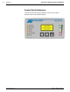
The LEDs provide the following indications during normal operations.
Using LED Indicators to Check Normal Operations
LED Description
STATUS GREEN to indicate the overall "health" of the reader.
(If RED, see Chapter 8, Troubleshooting.)
TRIGGER
Indicates the trigger input. The LED is activated upon trigger input
regardless of trigger source (incl. software trigger).
READ
Flashes red or green based upon the software criteria.
RX/TX LED for serial port 1. GREEN = Transmitting data
RED = Receiving data
NETWORK
Flashes red or green to indicate connection status.
For a Single TCP/IP connection, it indicates that a "host"
connection has been made to the reader.
For EtherNet/IP connection, it indicates "network" connection
status. This LED is software controlled.
For a Controller/Client multi-reader connection, it indicates
that all inter-reader communications (connections between
readers) are correctly functioning.
LINK
This LED is LINK indicator for Ethernet.
Flashes GREEN when connected to a network.
Bar Graph
(LED 1 - 5)
Scan quality indicator.
Flashes when parameters copied to/from mounting base.
LEDs stay on when Test/Diagnostic button C is pressed during
the laser shutoff procedure.
06-AL5010_Operations_R20.doc Accu-Sort Systems, Inc.