
Technical information


AccuLazr
™
AL5010 Product Line Manual Appendix C: AccuLazr™ User Interface 183
A3-AL5010_User Interface_R20.doc Accu-Sort Systems, Inc.
Controller indicates a problem with a Client connection.
RED indicates a Controller with incompatible settings tried to
itiate a Client connection.
4 – Indicates the status of the programmable
in
I/O 1 through I/O
relay I/O lines.
Read Quality – Graph 0-100) The large percentage bar maps
the values displayed on the reader bar graph. The graph
to
is a
ynamic measure of "how well” the bar code was read. d
Scans/Code – Indicates how many passes of the laser (scan
es) contributed to the reading of the code. lin
Code Position – Indicates the bar code's position in the reader's
can line (from zero to 4095). s
Read
Performance
e QQ (code
uality) value for each laser that read the bar code.
Code Quality (QQ) – Laser 1 / Laser 2 - Indicates th
q
Messages
ed here. This
primarily information on each bar code read.
reeze) the messages being displayed for better diagnostics.
rm a copy function.
aste the text into an external text program.
Diagnostic messages from the reader are display
is
Use the buttons below the Messages area to start and stop
(f
To copy text, highlight the text and then perfo
P
Belt Speed (FPM) – Displays the belt speed in feet per minute.
Box Length (inch) – Displays the box length in inches.
the extend front or extend back
ption in the Tracking screen.
gh
e system, then the Box Length is reported as 12 inches
The box length is influenced by
o
Example:
If the extend front is set to 2 and a 10 inch box is sent throu
th
Code Position (inch) – Displays the code position on the box in
ches. in
Box Information
cans/Trigger – Displays the number of scans per trigger cycle. S
imate distance from the Distance (in) – Displays the approx
scanner to the bar code in inches.
Message
Monitor
om any of the reader host ports (either serial or network).
monitor from the
ption group below the message monitor.
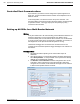
Use the Message Monitor to view the messages being sent
fr
Select the communication port you want to
o
Start Test Mode
ode. The scanner
will then read any readable bar code place in its beam.
Click Start Test Mode to put the scanner in timed test m