
Technical information


AccuLazr™ AL5010 Product Line Manual Appendix F: Installation Drawings 209
Installation Drawings
IMPORTANT: Although AL5010 is easy to install and setup, it is also very
robust in its capabilities. If you are interested in additional information on
product training, please contact us at 1-800-BAR-CODE.
Any application-specific drawings shipped with the equipment may
supersede the drawings provided in this appendix.
AL5010 Installation Drawings
The drawings provided in this appendix are useful when mechanically and
electrically installing the AccuLazr AL5010.
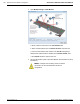
Mechanical Installation Drawings
AL5010 Scanner Mechanical Specification (111584)
AL5010 Mechanical Installation (111585)
AL5010 Mounting Dimensions (sheet 1)
AL5010 Mounting with Universal Mounting Bracket (sheet 2)
Kit, Universal Mounting Bracket, AL5010 (111620)
Basic Interface Module Specification (111632)
Enhanced Interface Module Specification (111634)
Photoeye Mounting (for Accu-Sort Structures) (41222)
Photoeye Mounting (24130)
Tachometer Mounting with Anti-Static Brush (102974)
Electrical Installation Drawings
Interconnect: AL5010 with Enhanced Interface Module (113490)
Interconnections of AL5010 (sheet 1)
Power, Trigger and Tachometer Options (sheet 2)
Start and End Trigger Photoeyes (sheet 3)
Computed Tach and Trigger (sheet 4)
Serial, DeviceNet or Profibus Communications (sheet 5)
AL5010 Controller / Client Interconnections (113492)
AL5010 Connector Pin-Outs Diagram (113493)
A6-AL5010_Installation_Drawings_R20.doc Accu-Sort Systems, Inc.