
Technical information


1 2 3 4 5
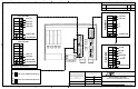
5 PORT SWITCH
SCANNER
NETWORK
POWER
TACH
TRIG
FIELD BUS
COM 1 / COM 2
I/O 1
I/O 2
I/O 3 I/O 4
SCANNER
NETWORK
POWER
TACH
TRIG
FIELD BUS
COM 1 / COM 2
I/O 1
I/O 2
I/O 3 I/O 4
12345678
8 7 6 5 4 3 2 1
A
B
C
DD
C
B
A
SHEET 1 OF 2
This document is provided for a specific purpose
and the disclosed information remains our
property. It may not be disclosed, copied, or
reproduced, except for specific purpose, without
Accu-Sort’s prior approval. This notice must
appear on any copy or reproduction of this
document.
©2003, ACCU-SORT SYSTEMS, inc
REVISIONS
REV
1 INITIAL RELEASE
BY DATE
NRS 11/23/10
ACCU-SORT SYSTEMS
TELFORD, PA. 18969 U S A
113492
11/23/10
DATEENGR
NRS
DRAWN
DATE
NRS
CHKD
NRS
DATE
11/23/10
11/23/10
DEPT
APP ENG
This is not a controlled copy unless stamped
“controlled copy” in red.
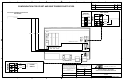
PHOTO EYE
SERIAL HOST
RS232 OR RS422 COM 1
RS232 OR RS422 COM 2
DWG NO:
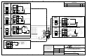
INTERCONNECT DRAWING
AL5010 CONTROLLER CLIENT
TACHOMETER
SCANNER
NETWORK
POWER
COM 1 / COM 2 TRIG
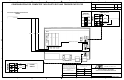
SCANNER
NETWORK
POWER
COM 1 / COM 2 TRIG
NETWORK
HOST AND/OR
SCANNER SETUP
CONTROLLER
AL5010
CLIENT
AL5010
Controller-Client configuration using Enhanced Interface Module for the controller and the Basic
Interface Module for the client. Refer to drawings 113490 INTERCONNECT DRAWING, AL5010
WITH ENHANCED MODULE and 113491 INTERCONNECT DRAWING, AL5010 WITH BASIC
MODULE for component wiring directions.
FLYING LEAD
POWER SUPPLY
FLYING LEAD
POWER SUPPLY