
Technical information


18 Mechanical Installation AccuLazr
™
AL5010 Product Line Manuals
Accu-Sort Systems, Inc. 03-AL5010_Mechanical_Installation_R20.doc
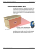
General Mounting Guidelines
As you plan and install the AL5010 barcode solution for your application, be
sure to keep the following mounting guidelines in mind:
Determine the proper orientation and position of the reader.
Leave adequate clearances for maintenance and wiring.
AL5010 Reader: ~ 1-inch [25 mm]
Required for scan head removal from mounting base.
Interface Modules: ~ 8-12 inches [203-305 mm]
Plan mechanical installation based on the application’s electrical require-
ments. See General Electrical Installation Guidelines in Chapter 4.
It is important that you follow all safety precautions when installing, setting
up, operating, maintaining, troubleshooting or replacing any Accu-Sort
products, parts or related equipment. See Chapter 2, Safety.
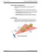
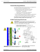
Reader Positioning: Fixed Laser
IMPORTANT: The AL5010 is able to decode barcodes at a variety of
angles; however significant angular distortion may degrade reading
performance. When positioning the reader, remember that the scan beam
exits the scan window parallel to the mounting base.
When mounting the AL5010, take into consideration your
application’s barcode orientation.
Mount the reader so that the scan beams will intersect barcodes.
IMPORTANT: To avoid the laser reflecting back onto itself
and lowering performance, install at a 10-degree skew.
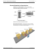
AL5010’s Range of Motion with Universal
Mounting Bracket (UMB)
10°
10°
0°