
Technical information


AccuLazr™ AL5010 Product Line Manual Electrical Installation 47
Trigger Connections
The AL5010 supports three trigger mode
s: hardware, software, and
continuous. When using hardware trigger, one or more input signals “trigger”
the reader. Software trigger is accomplished by sending a specific ASCII
message via serial or network communications. Continuous trigger requires
no external trigger.
When a hardware trigger (i.e., package detector) is required, Accu-Sort’s
retro-reflective photoeye (PN 100020569) is recommended.
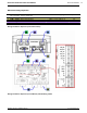
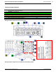
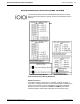
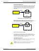
Wiring Trigger to the Enhanced Interface Module
Connect trigger wiring to the interface module terminal blocks.
Wire the Accu-Sort photoeye as shown below.
Enhanced Interface Module Basic Interface Module
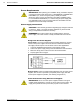
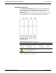
In applications using a photoeye other than the Accu-Sort standard, follow
the TRIGGER wiring table to assure proper wiring. The trigger must be able
to operate using the +24V DC source (24V) and not draw more than 100mA.
The trigger input must be able to sink (or source) 10mA at +24V DC.
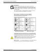
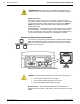
NOTE: To confirm the Trigger photoeye is functioning properly, watch the
Trigger LED while the photoeye’s beam is blocked. (See Chapter 5 for
details.) The Accu-Sort photoeye also includes a status LED.
Multiple Readers In con
troller/client applications, wire the trigger
photoeye
to the AL5010 set up as the controller. (See drawing in Appendix F.)
04-AL5010_Electrical_Installation_R20.doc Accu-Sort Systems, Inc.