PowerScan™ BC96XX Base Stations QUICK REFERENCE GUIDE Industrial Base Station/Charger for PowerScan 9600 Family Bar Code Readers
Datalogic S.r.l. Via S. Vitalino, 13 40012 Calderara di Reno (BO) Italia Telefono: +39 051 3147011 Fax: +39 051 3147205 ©2022 Datalogic S.p.A. and /or its affiliates. All rights reserved. Without limiting the rights under copyright, no part of this documentation may be reproduced, stored in or introduced into a retrieval system, or transmitted in any form or by any means, or for any purpose, without the express written permission of Datalogic S.p.A. and/or its affiliates.
TABLE OF CONTENTS END USER SOFTWARE LICENSE AGREEMENT............................................. IV Software Product Policy ......................................................................................... VII Using the BC96XX Base Station ................................................................... 1 base station Models..................................................................................... 2 Base Station Models .................................................................
EULA END USER SOFTWARE LICENSE AGREEMENT (EULA) FOR THE PowerScan™ PM96XX PRODUCT SERIES NOTICE TO END USER: BY DOWNLOADING OR INSTALLING THE SOFTWARE, OR BY USING THE DATALOGIC PRODUCT THAT INCLUDES THIS SOFTWARE, THE END USER CONSENTS TO BE BOUND BY THIS AGREEMENT.
EULA of the Software or such replacement, modified or upgraded version on your acceptance of such superseding Agreement. In addition, either party may terminate this Agreement at any time. Subject to the foregoing, termination shall be effective upon notice to the other party.
EULA End User specifically agrees not to export or re-export any of the Software: (i) to any country to which the U.S.
EULA For Europe, Middle East and Africa: This Agreement is governed by the laws of Italy. This Agreement and the rights of the parties hereunder shall be governed by and construed in accordance with the laws of Italy, without regard to the rules governing conflicts of law.
EULA NOTES VIII BC96XX BASE STATIONS
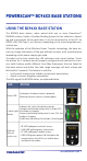
POWERSCAN™ BC96XX BASE STATIONS USING THE BC96XX BASE STATION The BC96XX base station, when paired with one or more PowerScan™ PM96XX readers, builds a Cordless Reading System for the collection, decoding and transmission of bar code data. It can be connected to a Host PC via RS232, USB, USB Type C, or Ethernet, depending on the interchangeable connection box.
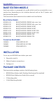
base station Models BASE STATION MODELS Each base station is composed of a cradle which must be connected to a connection box, depending on the interface desired and on the IP (water and dust) protection grade. The base station and connection box models are listed below. Base Station Models BC9600-433 BC9600-910 BC9630-433 BC9630-910 BC9631-433 BC9631-910 BC9680-433 BC9680-910 BASE/CHARGER 433MHZ w/o conn. box BASE/CHARGER 910MHZ w/o conn.
Mounting Instructions MOUNTING INSTRUCTIONS The base station can be either set on or mounted to a flat surface for desktop usage, or affixed vertically to a wall. Depending on the model, the appropriate connection box is already installed. PERMANENT MOUNTING For either desktop or wall mounting, the base station can be fastened directly to a flat surface using screws (not included). NOTE: When the base station is mounted on vertical surfaces, permanent mounting is always required.
Wall Mounting WALL MOUNTING The base station contains a reversible positioning tab for horizontal or vertical mounting. Figure 1 - Positioning Tab Desktop Positioning Tab (Horizontal) Wall Positioning Tab (Vertical) When shipped, the base station has the positioning tab installed in the Desktop position (horizontal). For vertical installation, the positioning tab must be rotated. Changing the Orientation of the Positioning Tab: 1. Remove the screw holding the tab in place. Keep the screw for reuse. 2.
Wall Mounting 3. Rotate the tab until you will see "WALL" tooth, put the rotated tab into place and secure it with the screw. 4. Remove the label (indicated in the figure below) from the base station: 5. Mount the Wall Mounting bracket onto the base station.
Portable Desktop Mounting PORTABLE DESKTOP MOUNTING For desktop mounting, if portability of the base station is required, the mounting plate can be used.
Portable Desktop Mounting 3. Align the base station with the mounting plate until you see the sphere inside the bigger hole on the left. 4. Move the base station down until the sphere is aligned with the smaller hole.
Portable Desktop Mounting Connection Box Fast Release - Mounting the Bracket 1. Remove the protective strips. 2. Unscrew the connection box from the base station. 3. Screw the mounting plate to the connection box. 2 3 4. Unlock the lever and remove the connection box from the base station. 5. Screw the connection box and mounting plate sub-assembly to a flat surface using four screws as shown in the figure below.
Portable Desktop Mounting 6. With the lever still unlocked, align the base station with the connection box until you see the sphere inside the bigger hole on the right. 7. Move the base station up until the sphere is aligned with the smaller hole, then lock the lever to secure the connection box.
System Connections SYSTEM CONNECTIONS CAUTION: Connections should always be made with power off. The BC9630 (BC9600 + CM9630 connection box) provides a multi-interface connector for connections to a host and a power supply connector for an external power supply. To unlock the multi-interface cable, first lift the lever and then extract the cable, as indicated by the label next to the lever.
System Connections RS232 BC9630 BC9631 USB The power supply is optional, the base station can be powered by the USB port. In this case, the full charging of an empty battery will take about 16 hours with an approved USB cable (type A) and 6.5 hours with an approved USB cable (type C) at ambient temperature. For intense usage and/or when the system is shut down during the night, the use of an external power supply is recommended.
System Connections BC9631 ETHERNET BC9680 Connecting and Disconnecting the Cables Connecting BC9630 cables Connect the multi-interface cable first, then connect the power adapter cable. Finally, power on the base station.
System Connections After connecting the power supply cable, secure it on the strain relief as shown in the figure below. Disconnecting BC9630 cables To disconnect the cables, power off the base station, unlock the lever and press down the cable clip using a pen or a similar tool.
System Connections Pull out the multi-interface cable and put the lever back into lock position. Lock position Connecting BC9631 multi-interface cable Unscrew the no-tool screw to open the front door, connect the multi-interface cable, close the door and screw it back. Unscrew Insert Screw To disconnect the multi-interface cable, open the front door, pull out the cable and screw the front door back.
System Connections Connecting BC9680 cables Connect the Ethernet cable and then connect the power adapter cable. Finally, power on the cradle and lock the power cable on the strain relief. To disconnect the cables, first unlock the power cable and then pull it out. To disconnect the Ethernet cable, use a flat screwdriver to unlock the Ethernet clip. CAUTION: Do not place two base stations too close to each other as shown in the figure below.
Configuration CONFIGURATION BC9680 Ethernet Models BC9680 configuration can be performed using the Datalogic Aladdin software configuration program or by reading configuration bar codes with the PowerScan™ PM96XX reader.
Technical Specifications TECHNICAL SPECIFICATIONS The following table contains Physical and Performance Characteristics, User Environment and Regulatory information. PHYSICAL CHARACTERISTICS Color Black Dimensions Height 9.8 cm (3.9'') Length 24.3 cm (9.6'') Width 10.
Technical Support RADIO CHARACTERISTICS Frequency working center 433MHz 910MHz Programmable Speed 19.2 kb/s 500 kb/s (default) 36.8 kb/s 500 kb/s (default) 100 m (at 500 kb/s) 150 m (at 19.2 kb/s) 180 m (at 500 kb/s) 230 m (at 36.8 kb/s, frequency hopping) 80 m (at 36.8 kb/s, fixed channel) Typical Range (in open air) Max number of devices per base station 16 NOTE: A radio coverage reduction is expected when the base station is charging a gun.
Warranty WARRANTY Datalogic warrants that the Products shall be free from defects in materials and workmanship under normal and proper use during the Warranty Period. Products are sold on the basis of specifications applicable at the time of manufacture and Datalogic has no obligation to modify or update Products once sold. The Warranty Period shall be three years from the date of shipment by Datalogic, unless otherwise agreed in an applicable writing by Datalogic.
©2022 Datalogic S.p.A. and /or its affiliates. • All rights reserved • Without limiting the rights under copyright, no part of this documentation may be reproduced, stored in or introduced into a retrieval system, or transmitted in any form or by any means, or for any purpose, without the express written permission of Datalogic S.p.A. and/or its affiliates • Datalogic and the Datalogic logo are registered trademarks of Datalogic S.p.A. in many countries, including the U.S. and the E.U. www.datalogic.