
Instruction manual

GENERAL FEATURES
2
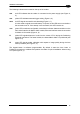
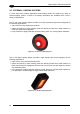
The following indicators are located on the top of the reader:
PWR red LED indicates that the reader is connected to the power supply (see Figure A,
5).
TRIG yellow LED indicates external trigger activity (Figure A, 6).
READ red LED signals successful code decoding (Figure A, 7).
It is also used to signal successful startup. At power on this LED turns on and after a
few seconds turns off. If the startup is not successful, this LED remains on.
COM green LED is software configurable. As default it indicates: data transmission on the
main serial interface for Matrix-20XX models; Ethernet interface external connection
for Matrix-21XX models (Figure A, 8).
F1 yellow LED signals distance of code from the center of FOV during the Positioning
(Optional) procedure. The faster it blinks, the better Matrix-2000™ is positioned (see
Figure A, 4).
F2 green LED signals reader calibration with respect to image quality during the Auto
Learn procedure (see Figure A, 2).
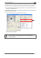
The keypad
button is software programmable. By default it starts the Auto Learn or
Positioning procedure to calibrate and position the reader for quick installation without using
a PC (see Figure A, 3).
15