
Instruction manual

MATRIX-2000™ REFERENCE MANUAL
5
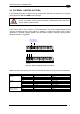
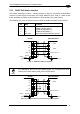
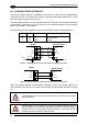
5.2 DB9-PIN CONNECTOR (RS232 AUXILIARY PORT)
There is also a separate 9-pin female D-sub connector for the Auxiliary port connection with
the following pinout:
5
1
9
6
Figure 62 - 9-pin female D-Sub Connector
9-pin female D-sub connector pinout
Pin Name Function
2 TX Transmitted data of auxiliary RS232
3 RX Received data of auxiliary RS232
5 GND Reference GND of auxiliary RS232
1,4,6,7,8,9 N.C. Not connected
CAUTION
If Matrix-2000™ is connected to a CBX with a BM100 Backup Module,
then the Matrix-2000™ 9-pin Auxiliary port connector cannot be used for
communication (i.e. configuration through VisiSet™). In this case use the
Auxiliary port 9-pin connector inside the CBX.
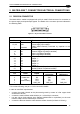
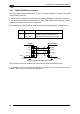
5.3 RJ45 8-PIN CONNECTOR (ETHERNET)
In Matrix-21XX models a RJ45 Modular Jack is provided for Ethernet connection. This
interface and the connector pinout (see the following table) are IEEE 802.3 10 BaseT and
IEEE 802.3u 100 BaseTx compliant. See par. 5.7 for connection details.
1
8
Figure 63 - RJ45 Modular Jack
RJ45 modular jack pinout
Pin Name Function
1 TX + Transmitted data (+)
2 TX - Transmitted data (-)
3 RX + Received data (+)
6 RX - Received data (-)
4,5,7,8 N.C. Not connected
44