
Instruction manual

MATRIX-2000™ REFERENCE MANUAL
5
5.6 AUXILIARY RS232 INTERFACE
The RS232 auxiliary interface is available for Point-to-Point, Pass Through or Master/Slave
connections. When it is connected to the host computer it allows both transmission of code
data and reader configuration by VisiSet™.
The parameters relative to the aux interface (baud rate, data bits, etc.) as well as particular
communication modes such as LOCAL ECHO can be defined through the Communication
folder of the VisiSet™ utility program.
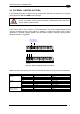
The auxiliary interface is available on both D-sub connectors with the following pinouts:
9-Pin 25-Pin Name Function
2
21 TX Transmitted data
3
20 RX Received data
5
23 GND Ground
MATRI
X
RX
TX
USER INTERFACE
TXD
RXD
GND
Ground
SHIELD
20
21
23
1
Earth Ground Earth Ground
Chassis
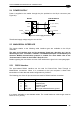
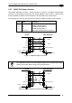
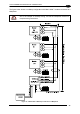
Figure 71 - RS232 Auxiliary Interface Connections Using 25-pin Connector
MATRI
X
3
RX
TX
2
USER INTERFACE
TXD
RXD
5
GND
Ground
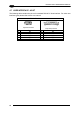
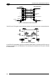
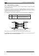
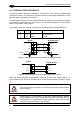
Figure 72 - RS232 Auxiliary Interface Connections Using 9-pin Connector
When the auxiliary interface is permanently connected as part of the system cabling, it is
recommended to use the 25-pin connector and connect the cable shield as shown in Figure
71.
CAUTION
Avoid simultaneous connection to 25-pin and 9-pin signals of the auxiliary
RS232 interface.
CAUTION
If Matrix-2000™ is connected to a CBX with a BM100 Backup Module,
then the Matrix-2000™ 9-pin Auxiliary port connector cannot be used for
communication (i.e. configuration through VisiSet™). In this case use the
Auxiliary port 9-pin connector inside the CBX.
50