
Instruction manual


MATRIX-2000™ REFERENCE MANUAL
6
6 TYPICAL LAYOUTS
The following typical layouts refer to system
hardware configurations. However, they also
require the correct setup of the software configuration parameters. Dotted lines in the figures
refer to optional hardware configurations within the particular layout.
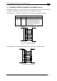
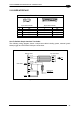
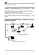
6.1 POINT-TO-POINT
In this layout the data is transmitted to the Host on the main serial interface.
The RS232 auxiliary interface can be used for reader configuration by connecting a laptop
computer running VisiSet™. Host Mode programming can be accomplished either through
the main interface or the Auxiliary interface.
In Local Echo communication mode, data is transmitted on the RS232 auxiliary interface
independently from the main interface selection.
When One Shot or Phase Mode operating mode is used, the reader can be activated by an
External Trigger (for example a pulse from a photoelectric sensor) when the object enters its
reading zone.
Configuration
PC
PG6000
CBX
CAB-Sxx
Host
1
Matrix-2000™
2
3
Main Serial Interface (RS232 or RS485 Full-Duplex)
Auxiliary Serial Interface (Local Echo) (RS232)
External Trigger (for One Shot or Phase Mode)
Figure 87 – Serial Interface Point-to-Point Layout
NOTE
Only one device at a time can be connected to the Matrix-2000™ Auxiliary
port, either through the reader 9-pin connector, CBX 9-
p
in connector or CBX
spring clamp connectors.
58