
Specifications

Matrix-2000™ Reference Manual
3
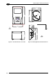
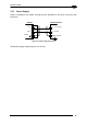
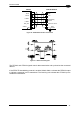
3.3 ELECTRICAL CONNECTIONS
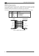
The Matrix-2000™ reader is equipped with a 25-pin male D-Sub connector for connection to
the power supply and input/output signals. The details of the connector pins are indicated in
the following table:
13
2514
1
Figure 36 - 25-pin male D-Sub Connector
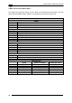
25-pin male D-sub connector pinout
Pin Name Function
1 SHIELD Cable shield internally connected by capacitor to the
chassis
20 RXAUX Received data of auxiliary RS232 (referred to GND)
21 TXAUX Transmitted data of auxiliary RS232 (referred to GND)
8 OUT 1+ Configurable digital output 1 - positive pin
22 OUT 1- Configurable digital output 1 - negative pin
11 OUT 2+ Configurable digital output 2 - positive pin
12 OUT 2- Configurable digital output 2 - negative pin
16 OUT 3 + Configurable digital output 3 - positive pin
17 OUT 3 - Configurable digital output 3 - negative pin
18 EXT_TRIG A External trigger (polarity insensitive)
19 EXT_TRIG B External trigger (polarity insensitive)
6 IN 2A Input signal 2 (polarity insensitive)
10 IN 2B Input signal 2 (polarity insensitive)
14, 15, 24 NC Not connected
9,13 VS Supply voltage - positive pin
23, 25 GND Supply voltage - negative pin
RS232 RS485
full-duplex
RS485
half-duplex
2 TX232 TX485+ RTX485+
3 Main interface RX232 RX485+
4 (see par. 3.3.2) RTS232 TX485- RTX485-
5 CTS232 RX485-
7 GND_ISO GND_ISO GND_ISO
26