
Specifications

INSTALLATION
3
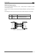
3.3.5 Inputs
Two opto-coupled and polarity insensitive inputs are available on the 25-pin connector. The
pinout is the following:
Pin Name Function
18 EXT_TRIG A External trigger (polarity insensitive)
19 EXT_TRIG B External trigger (polarity insensitive)
6 IN 2A Input signal 2 (polarity insensitive)
10 IN 2B Input signal 2 (polarity insensitive)
When current flows through the EXT_TRIG input, the yellow LED (Figure A, 6) is on.
The External Trigger can be used in One Shot Mode or in Phase Mode. Its main functions
are:
• acquisition trigger in One Shot Mode
• reading phase-ON/reading phase-OFF command in Phase Mode
The main functions of the general purpose Input 2 are:
• second external trigger in Phase Mode
• match code storage command when the Match Code option is enabled
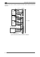
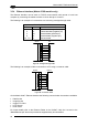
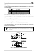
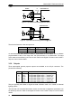
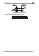
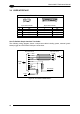
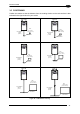
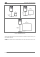
These inputs can be driven by either a PNP or NPN type command. The connections are
indicated in the following diagrams:
NOTE
Polarity insensitive inputs assure full functionality even if pins A and B are
exchanged.
USER INTERFACE
OUT
MATRIX
V
CC
A
Vext
B
GND
V
+
~
~
+
-
I
in
30 Vdc Max.
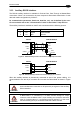
Figure 49 - Input PNP Command Using External Power
USER INTERFACE
MATRIX
V
CC
A
B
V
+
~
~
+
-
9
25
OUT
GND
GND
V
S
Figure 50 - Input PNP Command Using Matrix-2000™ Power
37