
Specifications

Matrix-2000™ Reference Manual
3
USER INTERFACE
VS
MATRIX
A
Vext
B
V
+
V
CC
~
~
+
-
GND
OUT
30 Vdc Max.
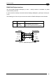
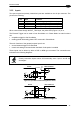
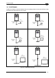
Figure 51 - Input NPN Command Using External Power
USER INTERFACE
VS
MATRIX
A
B
GND
V
+
V
CC
~
~
+
-
GND
9
OUT
25
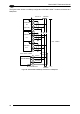
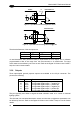
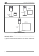
Figure 52 - Input NPN Command Using Matrix-2000™ Power
The electrical features of the two inputs are:
INPUT | V
AB
| Min. | V
AB
| Max. I
IN
Max
.
Open 0 V 2 V 0 mA
Closed 4.5 V 30 V 10 mA
An anti-disturbance filter (debounce filter) is implemented on both inputs, and is software
programmable to filter in the range from 100 microseconds to 10 milliseconds. The input
active state can be defined by the user as well. Refer to the Digital I/O folder in the VisiSet™
Help On Line for further details.
3.3.6 Outputs
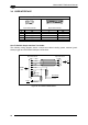
Three optocoupled general purpose outputs are available on the 25-pin connector. The
pinout is the following:
Pin Name Function
8 OUT1+ Configurable digital output 1 - positive pin
22 OUT1- Configurable digital output 1 - negative pin
11 OUT2+ Configurable digital output 2 - positive pin
12 OUT2- Configurable digital output 2 - negative pin
16 OUT3+ Configurable digital output 3 - positive pin
17 OUT3- Configurable digital output 3 - negative pin
They are typically used either to signal the data collection result or to control an external
lighting system.
The idle state, the activation/deactivation events and the other configuration parameters can
be defined by the user. Refer to the Digital I/O folder in the VisiSet™ Help On Line for further
details.
38