DS2100N Reference Manual
Datalogic Automation Srl Via S. Vitalino, 13 40012 - Lippo di Calderara di Reno Bologna - Italy DS2100N Reference Manual Ed.: 07/2007 ALL RIGHTS RESERVED Datalogic reserves the right to make modifications and improvements without prior notification. Datalogic shall not be liable for technical or editorial errors or omissions contained herein, nor for incidental or consequential damages resulting from the use of this material.
CONTENTS REFERENCES ............................................................................................................. v Conventions.................................................................................................................. v Reference Documentation ............................................................................................ v Services and Support ................................................................................................... v Patents...
3.6.5 Multiplexer Layout....................................................................................................... 48 4 4.1 4.1.1 4.1.2 4.2 4.2.1 4.2.2 4.3 4.3.1 4.4 READING FEATURES............................................................................................... 49 Advanced Code Builder (ACB) ................................................................................... 49 Important ACB Reading Conditions....................................................................
REFERENCES CONVENTIONS This manual uses the following conventions: “User” or “Operator” refers to anyone using a DS2100N. “Device” refers to the DS2100N. “You” refers to the System Administrator or Technical Support person using this manual to install, mount, operate, maintain or troubleshoot a DS2100N.
SAFETY REGULATIONS LASER SAFETY The following information is provided to comply with the rules imposed by international authorities and refers to the correct use of the DS2100N scanner. Standard Regulations This scanner utilizes a low-power laser diode. Although staring directly at the laser beam momentarily causes no known biological damage, avoid staring at the beam as one would with any very strong light source, such as the sun.
Disconnect the power supply when opening the device during maintenance or installation to avoid exposure to hazardous laser light. The laser diode used in this device is classified as a class 3B laser product according to EN 60825-1 regulations and as a Class IIIb laser product according to CDRH regulations.
ITALIANO Informazione degli utenti ai sensi della Direttiva Europea 2002/96/EC L’apparecchiatura che riporta il simbolo del bidone barrato deve essere smaltita, alla fine della sua vita utile, separatamente dai rifiuti urbani.
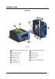
GENERAL VIEW DS2100N 4 5 6 3 2 1 7 10 9 8 11 Figure A 1 Warning and Device Class Labels 7 Laser Beam Output Window 2 "POWER ON" LED 8 "COM" LED 3 Mounting Holes 9 "STATUS" LED 4 "READY" LED 10 Push Button 5 "GOOD" LED 11 Accessory Mounting Holes 6 "TRIGGER" LED ix
x
RAPID CONFIGURATION 1 1 RAPID CONFIGURATION STEP 1 – CONNECT THE SYSTEM To connect the system in a Stand Alone configuration, you need the hardware indicated in Figure 1. In this layout the data is transmitted to the Host on the main serial interface. In Local Echo communication mode, data is transmitted on the RS232 auxiliary interface independently from the main interface selection.
DS2100N REFERENCE MANUAL 1 C-BOX 100/150 Pinout for DS2100N The table below gives the pinout of the C-BOX 100/150 terminal block connectors.
RAPID CONFIGURATION 1 STEP 2 – MOUNTING AND POSITIONING THE SYSTEM 1. To mount the DS2100N, use the mounting bracket to obtain the most suitable position for the reader as shown in the figures below. Skew Tilt Pitch Skew Figure 2 - Positioning with Mounting Bracket 2. When mounting the DS2100N take into consideration these three ideal label position angles: Pitch 0°, Skew 10° to 30° and Tilt 0°.
DS2100N REFERENCE MANUAL 1 STEP 3 – X-PRESS™ CONFIGURATION X-PRESS™ is the intuitive Human Machine Interface designed to improve ease of installation and maintenance.
RAPID CONFIGURATION 1 Auto Learn If you are configuring your scanner using X-PRESS™, you must start with the Auto Learn procedure. 1. Enter the Auto Learn function (F2) by pressing the X-PRESS™ push button. 2. Hold the push button pressed until the F2 LED is on. 3. Release the button to enter the Auto Learn function. Once entered, the reader starts a procedure to automatically detect and recognize barcodes (by type and length), which are presented to it (*).
DS2100N REFERENCE MANUAL 1 Auto Setup (Optional) At the end of the Auto Learn procedure, you have the possibility to follow the Auto Setup procedure to set up the reading parameters. 1. Enter the Auto Setup function (F3) by pressing the X-PRESS™ push button. 2. Hold the push button pressed until the F3 LED is on. 3. Release the button to enter the Auto Setup function. 4.
RAPID CONFIGURATION 1 STEP 4 – INSTALLING GENIUS™ CONFIGURATION PROGRAM Genius™ is a Datalogic scanner configuration tool providing several important advantages: • Wizard approach for new users; • Multi-language version; • Defined configuration directly stored in the reader; • Communication protocol independent from the physical interface allowing to consider the reader as a remote object to be configured and monitored.
DS2100N REFERENCE MANUAL 1 1. Select the Create a new configuration button. You will be guided through the configuration being asked to define the following parameters: a.
RAPID CONFIGURATION b. Operating mode selection and definition c.
DS2100N REFERENCE MANUAL 1 d. Hardware interface selection e. Output data format configuration The On Line operating Mode requires the reader to be connected to an external Presence Sensor using EXT TRIG/PS A and EXT TRIG/PS B inputs. The Automatic operating mode does not require connection to an external Presence Sensor. When working in this mode the reader is continuously scanning, while the reading phase is activated each time a barcode enters the reader reading zone.
RAPID CONFIGURATION 1 2. After defining the parameter values the following window appears allowing to complete the reader configuration as follows: • Saving the configuration to disk; • Switching to Advanced mode; • Sending the configuration to the scanner. 3. After sending the configuration to the scanner you have completed the configuration process. 4. By clicking Finish, the System Information window will be displayed with specific information concerning the scanner.
DS2100N REFERENCE MANUAL 1 STEP 5 – TEST MODE Use a code suitable to your application to test the system. Alternatively, you can use the Datalogic Test Chart (Code 39, Code Interleaved 2/5). 1. Enter the Test mode function (F1) by pressing the X-PRESS™ push button. 2. Hold the push button pressed until the F1 LED is on. 3. Release the button to enter the Test mode function.
RAPID CONFIGURATION 1 ADVANCED SCANNER CONFIGURATION For further details on advanced product configuration, refer to the complete Reference Manual on the installation CD-ROM or downloadable from the web site through this link: www.automation.datalogic.com/ds2100n. The following are alternative or advanced scanner configuration methods: Host Mode Programming The scanner can also be configured from a host computer using the Host Mode programming procedure, by commands via the serial interface.
DS2100N REFERENCE MANUAL 2 2 INTRODUCTION 2.1 PRODUCT DESCRIPTION The DS2100N laser scanner satisfies the most advanced needs of a wide range of users. It has been developed focusing on the realistic requirements of its target market. The outstanding result is an extremely compact, cost-effective and easy to use industrial scanner. Standard Application Program A standard application program is factory-loaded onto the DS2100N.
INTRODUCTION 2.1.1 2 Indicators The five LEDs on the side of the scanner indicate the following: READY (green) This LED indicates the device is ready to operate. (Figure A, 4) GOOD (green) This LED confirms successful reading. (Figure A, 5) TRIGGER (yellow) This LED indicates the status of the reading phase. (Figure A, 6) COM (yellow) This LED indicates active communication on main serial port. (Figure A, 8) STATUS (red) This LED indicates a NO READ result.
DS2100N REFERENCE MANUAL 2 ID-NET™ interface allows connection of scanners reading objects placed on independent conveyors. All scanners are typically located far away from each other and they use a dedicated presence sensor. At the end of each reading phase, each scanner transmits its own data message to the host. Thanks to ID-NET™, data collection among readers is accomplished at a high speed without the need of external multiplexing device.
INTRODUCTION 2 2.3 X-PRESS™ HUMAN MACHINE INTERFACE X-PRESS™ is the intuitive Human Machine Interface designed with the precise goal of improving ease of installation and maintenance.
DS2100N REFERENCE MANUAL 2 2.3.2 X-PRESS™ Functions Quick access to the following functions is provided by an easy procedure using the push button: 1 – Press the button (the F0 LED will give a visual feedback). 2 – Hold the button until the specific function LED is on (F1, F2 or F3). 3 – Release the button to enter the specific function.
INTRODUCTION 2 AutoLearn (F2) Function Once entered, the reader starts a procedure to automatically detect and recognize barcodes (by type and length), which are presented to it1. The laser turns on and the TRIGGER LED blinks to indicate the ongoing process. The procedure is as follows: - place the desired barcode on the scanline. - wait until the TRIGGER LED stays steady on (indicating the reader has detected the barcode).
DS2100N REFERENCE MANUAL 2 2.4 MODEL DESCRIPTION The DS2100N scanner is available in versions that differ in regard to the following parameters: • Resolution • Performance • Linear or raster reading DS2100N - X X X X Optical Resolution 1 = Standard resolution 2 = High resolution Communication Interface 2= RS232/RS485main + RS232 aux + RS485 ID-NET™ Optic Version 0 = Linear 1 = Raster R1 Performance 0 = Standard 4 = High Performance The following tables display each version’s reading performance.
INTRODUCTION 2 2.
DS2100N REFERENCE MANUAL 3 3 INSTALLATION 3.1 PACKAGE CONTENTS Verify that the DS2100N reader and all the parts supplied with the equipment are present and intact when opening the packaging; the list of parts includes: • DS2100N reader with cable • DS2100N Quick Guide • Barcode Test Chart (PCS = 0.
INSTALLATION 3 3.2 MECHANICAL INSTALLATION DS2100N can be installed to operate in different positions. The four screw holes (M4 x 5) on the body of the reader are for mechanical fixture (Figure A, 3). The diagrams below give the overall dimensions of the scanner and mounting bracket and may be used for installation. Refer to par. 3.5 for correct positioning. 84 3.31 23.3* 0.92 4 0.16 10.3 0.41 10.3 0.41 14 0.55 14.7 0.58 M 4 n° 4 DS2100N F3 READY GOOD 40 1.57 68 2.68 46 1.81 40 1.
DS2100N REFERENCE MANUAL 3 3.2.
INSTALLATION 3.2.2 3 Mounting Scanner Accessories GFC-2X00s are accessory deflection mirrors available on request for DS2100N. • The GFC-2000 is a 75° deflection mirror • The GFC-2100 is a 90° deflection mirror The reading position with respect to the scanner is shown below for each mirror. GFC-2000 75° ± 2° Laser Beam 90° ± 2° GFC-2100 Figure 14 - GFC-2X00 Laser Beam Output Position The installation of the deflection mirror is very easy (Figure 15).
DS2100N REFERENCE MANUAL 3 3.3 ELECTRICAL CONNECTIONS All DS2100N models are equipped with a cable terminated by a 25-pin female D-sub connector for connection to the power supply and input/output signals. The details of the connector pins are indicated in the following table. CAUTION Do not connect GND and SGND to different (external) ground references. GND and SGND are internally connected through filtering circuitry which can be permanently damaged if subjected to voltage drops over 0.8 Vdc.
INSTALLATION 3 The table below gives the pinout of the C-BOX 100/150 terminal block connectors.
DS2100N REFERENCE MANUAL 3 3.3.1 Power Supply Power can be supplied to the scanner through the pins provided on the 25-pin connector used for communication with the host (Figure 17): USER INTERFACE DS2100N 13 25 1 VS V+ (10 - 30 Vdc) GND VGND CHASSIS CHASSIS Earth Ground Figure 17 - Power Supply Connections The power must be between 10 and 30 Vdc only. It is recommended to connect pin 1 (CHASSIS) to a common earth ground. 3.3.
INSTALLATION 3 RS232 Interface The serial interface is used in this case for point-to-point connections; it handles communication with the host computer and allows both transmission of code data and the programming of the scanner. This is the default setting. The following pins are used for RS232 interface connection: Pin 2 3 4 5 7 Name TX232 RX232 RTS232 CTS232 SGND Function Transmit Data Receive Data Request To Send Clear To Send Signal Ground It is always advisable to use shielded cables.
DS2100N REFERENCE MANUAL 3 If the RTS/CTS handshaking protocol is enabled, the DS2100N activates the RTS232 output to indicate a message is to be transmitted. The receiving unit activates the CTS232 input to enable the transmission.
INSTALLATION 3 RS485 Half-Duplex Interface The RS485 half-duplex (3 wires + shield) interface is used for polled communication protocols. It can be used in a master/slave layout or for Multidrop connections with a Datalogic Multiplexer, (see par. 3.6.4 and 3.6.5) exploiting a proprietary protocol based on polled mode called MUX32 protocol, where a master device polls slave devices to collect data.
DS2100N REFERENCE MANUAL 3 120 Ohm max 2 m DS2X00N #x (up to 31) max 1200 m DS2X00N #1 RTX485 + DS2X00N #0 CHASSIS RTX485 SGND Three wires + shield RTX485 + RTX485 MULTIPLEXER RS485 REF SHIELD 120 Ohm Figure 23 - DS2100N Multidrop Connection to a Multiplexer 20 mA Current Loop Interface (C-Box 100/150 w/INT-30 Accessory Only) To adapt DS2100N to 20 mA Current Loop interfaces, it must be connected to a C-Box 100/150, which is equipped with an INT-30 (20 mA Current Loop adapter accessory board).
INSTALLATION 3.3.3 3 ID-NET™ Interface C-BOX 100/150 Pin 38 36 39 Name ID-NET+ ID-NETGND Function High speed internal network+ High speed internal networkGround ID-NET™ Cables The following instructions are referred to Figure 25, Figure 26 and Figure 27. • The general cable type specifications are: CAT5 twisted pair + additional CAT5 twisted pair, shielded cable AWG 24 (or AWG 22).
DS2100N REFERENCE MANUAL 3 ID-NET™ Response Time The following figure shows the response time of the ID-NET™ network. This time is defined as the period between the Trigger activation and the beginning of data transmission to the Host.
INSTALLATION 3 Figure 25 – ID-NET™ Network Connections with isolated power blocks 35
3 DS2100N REFERENCE MANUAL Figure 26 - ID-NET™ Network Connections with Common Power Branch Network 36
INSTALLATION 3 Figure 27 – ID-NET™ Network Connections with Common Power Star Network 37
DS2100N REFERENCE MANUAL 3 ID-NET™ Network Termination The network must be properly terminated by a 120 Ohm resistor in the C-BOX 100/150 of the first and last scanner of the network. 3.3.4 Auxiliary RS232 Interface The auxiliary serial interface is used exclusively for RS232 point-to-point connections. The parameters relative to the aux interface (baud rate, data bits, etc.
INSTALLATION 3.3.5 3 Inputs The inputs available on the connector supplied with the scanner are the pins relative to the External Trigger and generic input, as indicated below: Pin 18 19 10 25 Name EXT TRIG A EXT TRIG B IN2GND Function External Trigger A (polarity insensitive) External Trigger B (polarity insensitive) Input 2 Power Ground/IN2 Reference The External Trigger input is used in the On-Line operating Mode and tells the scanner to scan for a code.
DS2100N REFERENCE MANUAL 3 EXTERNAL TRIGGER INPUT DS2100N EXTERNAL TRIGGER VS 9 V 18 EXT TRIGA VCC + ~ ~ 19 EXT TRIGB 25 GND Signal Ground Figure 31 - External Trigger NPN using DS2100N power Vext 30 Vdc max.
INSTALLATION 3 Code Verifier If the DS2100N is used as a Code Verifier, it is possible to indicate to the scanner what code to store as the verifier code by means of an external hardware input. The Code Verifier parameter must be enabled and the configuration parameters to allow correct Code Type reading must be saved to the scanner in order to read the verifier code. The next read code will non-volatile (Flash) memory. 3.3.
DS2100N REFERENCE MANUAL 3 3.4 USER INTERFACE The following table contains the pinout for standard RS232 PC Host interface. For other user interface types please refer to their own manual.
INSTALLATION 3 3.5 POSITIONING The DS2100N scanner is able to decode moving barcode labels at a variety of angles, however significant angular distortion may degrade reading performance. When mounting the DS2100N take into consideration these three ideal label position angles: Pitch 0°, Skew 10° to 30° and Tilt 0°. Follow the suggestions for the best orientation: The Pitch angle is represented by the value P in Figure 35. Position the reader in order to minimize the Pitch angle.
DS2100N REFERENCE MANUAL 3 The Tilt angle is represented by the value T in Figure 37. Position the reader in order to minimize the Tilt angle. T Figure 37 - Tilt Angle By using the ACB (Advanced Code Builder) software parameter, the tilt angle is less critical and can be decoded even if the scan line doesn’t cross the entire code. See par. 3.1 or the Help On Line for details. 3.6 TYPICAL LAYOUTS The following typical layouts refer to system hardware configurations.
INSTALLATION 3.6.2 3 Pass-Through Pass-through mode allows two or more devices to be connected to a single external serial interface. Each DS2100N transmits the messages received by the Auxiliary interface onto the Main interface. All messages will be passed through this chain to the host. When On-Line Operating mode is used, the scanner is activated by an External Trigger (photoelectric sensor) when the object enters its reading zone.
DS2100N REFERENCE MANUAL 3 The main and auxiliary ports are connected as shown in the figure below.
INSTALLATION 3.6.4 3 RS232 Master/Slave The RS232 master/slave connection is used to collect data from several scanners to build either a multi-point or a multi-sided reading system; there can be one master and up to 9 slaves connected together. The Slave scanners use RS232 only on the main and auxiliary serial interfaces. Each slave DS2100N transmits the messages received by the auxiliary interface onto the main interface. All messages will be passed through this chain to the Master.
DS2100N REFERENCE MANUAL 3 3.6.5 Multiplexer Layout Each scanner is connected to a Multiplexer (for example MX4000) with the RS485 halfduplex main interface.
READING FEATURES 4 4 READING FEATURES 4.1 ADVANCED CODE BUILDER (ACB) In addition to linear reading, the Advanced Code Builder (ACB) allows code reading by “stitching” together two partial reads of it. ACB is not as powerful as Advanced Code Reconstruction due to limits on tilt angle, speed and Multi-label function; but it is effective in the case of close-to-linear, small height codes, damaged codes, or poor print quality codes.
DS2100N REFERENCE MANUAL 4 4.1.1 Important ACB Reading Conditions • Do not use ACB for omni-directional reading stations. • ACB can be activated for each symbology independently from the others. • ACB requires that the code be in movement with respect to the scanner. • ACB requires fixed length barcode reading. • The codes read with ACB enabled must pass in front of the scanner one at a time.
READING FEATURES 4.2.1 4 Step-Ladder Mode If scanning is perpendicular to the code motion direction (Figure 44), the number of effective scans performed by the reader is given by the following formula: SN = [(LH/LS) * SS] – 2 Where: SN LH LS SS = = = = number of effective scans label height (in mm) label movement speed in (mm/s) number of scans per second Direction of code movement at LS speed DS2100N LH Laser beam Figure 44 - "Step-Ladder" Scanning Mode For example, the DS2100N (500 scans/sec.
DS2100N REFERENCE MANUAL 4 4.2.
READING FEATURES 4 4.3 PERFORMANCE The DS2100N scanner is available in different versions according to the reading performance. Version 12X0 12X4 22X0 22X4 Max Code Resolution Speed mm (mils) 0.20 (8) 0.15 (6) 0.15 (6) 0.12 (5) scans/s 500 to 800 800 to 1000 500 to 800 800 to 1000 Version Reading Distance 12X0 12X4 22X0 22X4 40 mm (1.6 in) - 300 mm (11.8 in) on 0.50 mm (20 mils) codes 50 mm (1.8 in) - 310 mm (11.8 in) on 0.50 mm (20 mils) codes 30 mm (1.2 in) - 90 mm (3.5 in) on 0.
DS2100N REFERENCE MANUAL 4 4.4 READING DIAGRAMS DS2100N-1200 (Standard Resolution, 500 scans/s) 0 0 5 1 20 2 40 3 60 4 5 6 7 8 9 10 11 100 80 3 60 2 40 1 20 0 0 1 20 0.20 mm (8 mils) 0.30 mm (12 mils) 0.35 mm (14 mils) 40 2 60 3 80 4 100 5 (in) 120 (mm) NOTE: (0,0) is the center of the laser beam output window.
READING FEATURES 4 DS2100N-1200 Reading Distance vs Scanning Speed Distance 0 0 1 20 2 40 3 60 4 5 6 7 8 9 10 11 12 (in) 80 100 120 140 160 180 200 220 240 260 280 300 (mm) 0.50 mm 0.35 mm 0.30 mm 0.
DS2100N REFERENCE MANUAL 4 DS2100N-2200 (High resolution, 500 scans/s) 0 0 1 10 20 2 30 40 50 3 60 70 4 80 5 90 100 110 120 130 60 2 50 40 30 ≥ 0.30 mm (12 mils) 1 20 0.15 mm (6 mils) 10 0 0 10 20 1 0.20 mm (8 mils) 30 40 2 (in) 50 60 (mm) NOTE: (0,0) is the center of the laser beam output window. CONDITIONS Optic Version Code PCS "Pitch" angle "Skew" angle "Tilt" angle *Code Reading Condition = = = = = = = * Parameter selectable in Genius™ 56 Linear Interleaved 2/5 or Code 39 0.
READING FEATURES 4 DS2100N-2200 Reading Distance vs Scanning Speed Distance 0 0 1 10 20 2 30 40 50 3 60 70 4 80 5 90 100 110 120 130 (in) (mm) 0.30 mm 0.20 mm 0.
DS2100N REFERENCE MANUAL 4 DS2100N-1204 High Performance (Standard Resolution, 1000 scans/s) 0 0 5 4 1 20 2 40 3 60 4 5 6 7 8 9 10 11 12 (in) 80 100 120 140 160 180 200 220 240 260 280 300 (mm) 120 100 80 3 60 2 40 1 20 0 0 1 20 0.15 mm (6 mils) 0.20 mm (8 mils) 0.30 mm (12 mils) ≥ 0.50 mm (20 mils) 40 2 60 3 80 4 100 5 (in) 120 (mm) NOTE: (0,0) is the center of the laser beam output window.
NOME MANUALE/NOME CAPITOLO 1 5 MAINTENANCE 5.1 CLEANING Clean the laser beam output window periodically for continued correct operation of the reader. Dust, dirt, etc. on the window may alter the reading performance. Repeat the operation frequently in particularly dirty environments. Use soft material and alcohol to clean the window and avoid any abrasive substances. Clean the window of the DS2100N when the scanner is turned off or, at least, when the laser beam is deactivated.
6 DS2100N REFERENCE MANUAL 6 TROUBLESHOOTING 6.1 GENERAL GUIDELINES When wiring the device, pay careful attention to the pin number of the signals and whether you are referring to the scanner connector or to the C-BOX 100/150 spring clamp connectors. If you need information about a certain reader parameter you can refer to the Genius™program help files.
TROUBLESHOOTING 6 TROUBLESHOOTING GUIDE Problem Power On: the “Power On”/”Ready” LED is not lit Suggestions Is power connected? If using a power adapter (like PG 220), is it connected to a wall outlet? If using rail power, does rail have power? If using C-Box 100, does it have power (check switch and LED)? Measure voltage either at pin 13 and pin 25 (for 25-pin connector) or at spring clamp 1 and 2 (for C-BOX 100).
DS2100N REFERENCE MANUAL 6 TROUBLESHOOTING GUIDE Problem Reading: Not possible to read the target barcode (always returns No Read) Suggestions Check synchronization of reading pulse with object to read: Is the scan line correctly positioned? Place barcode in the center of scan line and run TEST MODE (selectable by Genius™ as an Operating Mode).
TECHNICAL FEATURES 7 7 TECHNICAL FEATURES ELECTRICAL FEATURES Input Power Supply Voltage Power consumption max. Serial Interfaces Main Serial Interface Baudrate Auxiliary Baudrate ID-NET™ Baudrate Inputs External Trigger IN2 Voltage DS2100N-XXX0 DS2100N-XXX4 10 to 30 Vdc 3.5 W 5W Sw programmable: RS232; RS485 FD and HD (20 mA C.L. only with C-Box 100 and INT-30 accessory) 1200 – 115200 RS232 1200 - 115200 RS485 Half-duplex Up to 500000 Optocoupled, polarity insensitive not-optocoupled NPN only Ext.
DS2100N REFERENCE MANUAL 7 SOFTWARE FEATURES READABLE CODES * EAN/UPC (including Add-on 2 and Add-on 5) * Code 93 * 2/5 Interleaved * Code 128 * Code 39 (Standard and Full ASCII) * EAN 128 * Codabar ISBT 128 *ABC Codabar Pharmacode *ACB Readable. Other symbologies available on request.
GLOSSARY ACB (Advanced Code Builder) Advanced Code Builder (ACB) allows code reading by “stitching” together two partial reads of it. ACB is effective in reading codes positioned close-to-linear, small height codes, damaged codes, or poor print quality codes. See par. 4.1. Aperture Term used on the required CDRH warning labels to describe the laser exit window. Barcode A pattern of variable-width bars and spaces which represents numeric or alphanumeric data in machine-readable form.
Full Duplex Simultaneous, two-way, independent transmission in both directions. Half Duplex Transmission in either direction, but not simultaneously. Host A computer that serves other terminals in a network, providing services such as network control, database access, special programs, supervisory programs, or programming languages. Interface A shared boundary defined by common physical interconnection characteristics, signal characteristics and meanings of interchanged signals.
RS232 Interface between data terminal equipment and data communication equipment employing serial binary data interchange. RS485 Interface that specifies the electrical characteristics of generators and receivers for use in balanced digital multipoint systems such as on a Multidrop line. Scanner A device that examines a printed pattern (barcode) and either passes the uninterpreted data to a decoder or decodes the data and passes it onto the Host system.
INDEX A Accessories; 21 Advanced Code Builder (ACB); 49; 50 Auxiliary RS232 Interface; 38 C CE Compliance; vii Cleaning; 59 Code Verifier; 41 Current Loop Interface; 32 D DS2100N Description; 14 E Electrical Connections; 26 G General View; ix Glossary; 65 I ID-NET™; 45 ID-NET™ Cables; 33 ID-NET™ Interface; 33 ID-NET™ Network Termination; 38 ID-NET™ Response Time; 34 Inputs; 39 Installation; 22 L Laser Safety; vi LEDs; 15 Linear Code Reading; 50 M Main Serial Interface; 28 Mechanical Installation; 23 Model D
DECLARATION OF CONFORMITY 07 Datalogic Automation S.r.l. Via S.
www.automation.datalogic.