
Installation manual


INTRODUCTION
2
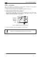
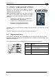
2.1.1 Indicators
The five LEDs on the side of the scanner indicate the following:
READY
(green)
This LED indicates the device is ready to operate. (
Figure A, 4)
GOOD
(green)
This LED confirms successful reading. (
Figure A, 5)
TRIGGER
(yellow)
This LED indicates the status of the reading phase. (
Figure A, 6)
COM
(yellow)
This LED indicates active communication on main serial port.
(
Figure A, 8)
STATUS
(red)
This LED indicates a NO READ result. (
Figure A, 9)
During the reader startup (reset or restart phase), all the LEDs blink for one second.
On the back of the reader near the cable, the “POWER ON” LED indicates the laser scanner
is correctly powered.
The screw holes on the body of the reader are for mechanical fixture (
Figure A, 3).
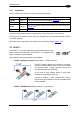
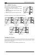
2.2 ID-NET™
The ID-NET™ is a built-in high-speed interface dedicated for high-
speed scanner interconnection. The ID-NET™ is in addition to the
Main and Auxiliary serial interfaces.
The following network configurations are available:
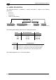
ID-NET™ M/S Synchronized: Single station – multiple scanners
ID-NET™ interface allows local connection of multiple
scanners reading different sides of the same target.
A
ll scanners share a single presence sensor and
activate/deactivate simultaneously.
At the end of each reading phase a single data
message is transmitted to the host.
Thanks to ID-NET™, data communication among
scanners is highly efficient so that an immediate result
will be available.
ID-NET™ M/S Multidata: Multiple stations – single scanner
15