STANDARD BHS AIRPORT ARRAYS AND REDUNDANT SYSTEMS Installation Manual
Datalogic Automation Srl Via Lavino, 265 40050 - Monte S. Pietro Bologna - Italy Standard BHS Airport Arrays and Redundant Systems Installation Manual Ed.: 10/2013 © 2011 - 2013 Datalogic Automation S.r.l. ALL RIGHTS RESERVED. Protected to the fullest extent under U.S. and international laws. Copying, or altering of this document is prohibited without express written consent from Datalogic Automation S.r.l. Datalogic and the Datalogic logo are registered trademarks of Datalogic S.p.A.
CONTENTS 1 1.1 1.2 1.3 1.4 1.5 BHS AIRPORT ARRAYS ........................................................................................... 1 General Description .................................................................................................... 1 Standard Station ......................................................................................................... 1 Redundant System (REDS) Station ............................................................................
5.1.3 5.2 5.3 5.3.1 5.3.2 5.4 5.5 5.5.1 5.6 5.7 DARP™ Restore ....................................................................................................... 35 Maintenance – Level 2 .............................................................................................. 36 Troubleshooting ........................................................................................................ 36 SC6000 Troubleshooting ...........................................................................
Required Resources: ................................................................................................ 64 Test Procedure: ........................................................................................................ 65 Results: ..................................................................................................................... 65 Short Report .............................................................................................................
vi
BHS AIRPORT ARRAYS 1 1 BHS AIRPORT ARRAYS 1.1 GENERAL DESCRIPTION There are two different types of Stations: T-Label and L-Label. T-Label Station These stations are usually needed when the IATA T-Labels are present. The T-Label presents 2 codes one at 90° respect to the other. In this case the X-pattern is not needed because if one code is not read it is always possible to read the other because it is at 90° with respect to the no read code.
BHS AND REDS INSTALLATION MANUAL 1 1.4 TYPICAL STATION PARAMETERS Conveyor Width: 1000 mm Conveyor Height: 800 mm Conveyor Speed: 2.5 m/s or higher Package Height: 700 mm max. Code Types: IATA 2/5IL 0.5mm module size Ratio=2:1 or greater Code Quality: ANSI Grade A or B. NOTE For further details about Hardware or Software explanations, please refer to the relative Reference Manual (PWO-480, SC6000, DS8100A, DX8200A and the GENIUS™ SW configuration program Help On-Line).
BHS AIRPORT ARRAYS 1 Standard Package Order Codes: 9K3L01068 BHS-Standard Mounting Frame 932402779 BHS-1500 Air T-Code 5-Side Tilt Tray 932402780 BHS-1600 Air T-Code 6-Side Tilt Tray 932402781 BHS-2500 Air Lin-Code 5-Side Tilt Tray 932402782 BHS-2600 Air Lin-Code 6-Side Tilt Tray 932402783 BHS-1510 Air T-Code 5-Side Belt Conv 932402784 BHS-1610 Air T-Code 6-Side Belt Conv 932402785 BHS-2510 Air Lin-Code 5-Side Belt Conv 932402786 BHS-2610 Air Lin-Code 6-Side Belt Conv 932402787 BHS-2611
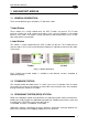
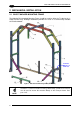
BHS AND REDS INSTALLATION MANUAL 2 2 MECHANICAL INSTALLATION 2.1 BHS STANDARD MOUNTING FRAME The following BHS Standard Mounting Frame should be used for either the T-Label or the LLabel Scanner Array. Datalogic Automation provides this frame as a commercially available kit (PN 9K3L01068). Install the PWO here on Profile #9. Figure 3 - BHS Standard Mounting Frame (9K3L01068) NOTE 4 Profile #7 is used for encoder mounting.
MECHANICAL INSTALLATION 2 BHS Standard Mounting Frame Bill Of Materials: Drawing Ref.
BHS AND REDS INSTALLATION MANUAL 2 2.2 GENERAL SCANNER MOUNTING For correct cable positioning and routing see par. 3.4 and par. 3.8. NOTE 2.2.
MECHANICAL INSTALLATION 2.2.2 2 Scanner Positioning Each scanner is labeled with a letter that indicates its position on the frame, see par. 2.3 or 2.4 for the correct scanner position. This is possible because the scanner Lonworks nodes and other parameters are already pre-configured. Figure 5 - Example Scanner Positioning 2.2.
BHS AND REDS INSTALLATION MANUAL 2 2.2.4 DX8200A Reference Point Stops One pair of washers and one pair of spacers (reference point stops) are provided with the DX8200A. They are intended to be mounted to the Reading Station Frame using Bosch Tbolts and nuts to create 2 stops which can be used to facilitate DX8200A mounting, positioning and replacing. Figure 7 - Reference Point Stops 2.2.5 Alternative Encoder Mounting When used, the encoder is normally mounted to Profile #7 in Figure 3.
MECHANICAL INSTALLATION 2 2.3 AIRPORT SCANNER ARRAY IATA T-LABEL D E F C B G H A Figure 9 - BHS 1610 T-Label Airport Scanner Array BHS 1610 Air T-Code 6-Side Belt Conv Order Code: 932402784 Bill Of Materials: Qty 1 1 8 2 1 1 1 3 5 1 1 1 Device SC6000-1200 UNIV. CONTROLLER, ETH PWO-480 POWER & CONNECT SYSTEM 480W DS8100A-3002, LOW RES, LIN.
BHS AND REDS INSTALLATION MANUAL 2 Frame Height note 1 Conveyor Height Min Bottom Scanner Distance note 2 Figure 10 - BHS 1610 T-Label Airport Scanner Array Front View Note 1: the drawing refers to a conveyor height of 800 mm. If the height is different, all the height measures change accordingly.
MECHANICAL INSTALLATION 2 note 1 Conveyor Direction Figure 11 - BHS 1610 T-Label Airport Scanner Array Side View Note 1: the photocell and its reflector must be mounted directly on the conveyor structure at 400 mm from the left upright. Suggested Standard Spare Products Device Code Qty (No. of stations) (1..6) (6..20) (21..40) 3 DS8100A-3002, LOW RES, LIN., BHS 932402758 1 2 SC6000-1200 UNIV.
BHS AND REDS INSTALLATION MANUAL 2 2.4 AIRPORT SCANNER ARRAY IATA L-LABEL E D B F C G A H Figure 12 - BHS 2610 L-Label Airport Scanner Array BHS 2610 Air Lin-Code 6-Side Belt Conv Order Code: 932402786 Bill Of Materials: Qty 1 1 4 4 2 1 1 1 3 5 1 1 1 Device SC6000-1200 UNIV. CONTROLLER, ETH PWO-480 POWER & CONNECT SYSTEM 480W DS8100A-3002, LOW RES, LIN.
MECHANICAL INSTALLATION 2 Reference Stops note 1 Frame Height note 2 Reference Stops note 1 Reference Stops note 1 Conveyor Height Min Bottom Scanner Distance note 3 Figure 13 - BHS 2610 L-Label Airport Scanner Array Front View Note 1: the arrows indicate the DX8200A reference point stops. Note 2: the drawing refers to a conveyor height of 800 mm. If the height is different, all the height measures change accordingly.
BHS AND REDS INSTALLATION MANUAL 2 note 1 Conveyor Direction Figure 14 - BHS 2610 L-Label Airport Scanner Array Side View Note 1: the photocell and its reflector must be mounted directly on the conveyor structure at 400 mm from the left upright. Suggested Standard Spare Products Device Code Qty (No. of stations) (1..6) (6..20) (21..40) 932402758 1 2 3 DX8200A-3002, LOW RES, BHS 936201032 1 2 SC6000-1200 UNIV.
CONNECTIONS 3 3 CONNECTIONS The SC6000 controller and the PWO in combination with DS8100A and DX8200A readers provide an easy way to build-up a reading station in terms of connections and setting of all system parameters. 3.1 HOST COMPUTER CONNECTIONS The Host computer can be connected to the reading system in two ways: directly to the SC6000 using the proper connectors available on the bottom panel.
BHS AND REDS INSTALLATION MANUAL 3 3.2 SC6000 TO PWO CONNECTIONS The SC6000 is connected to the PWO by two 25-pin cables: CAB-SC6013 is used to bring power and provide scanner network connectivity CAB-SC6003 is used to connect to all the necessary input and output signals If the Host is connected inside the PWO then the CAB-SC6103 is also used to connect the the SC6000 to the PWO.
CONNECTIONS 3 3.3 READER CONNECTIONS The readers are connected to the “LonWorks” network through 4 x “8K” connectors available on the PWO. Each “8K” connector supports a branch, each branch is made up of 4 readers maximum (total 16 readers max). Connection between scanners and PWO is performed by CAB-810X. The possible lengths are 1.2m, 2.5m and 5m. The readers must be connected alternatively as shown in the figures below, this allows reading on all sides even if one of the branches is not working.
BHS AND REDS INSTALLATION MANUAL 3 3.
CONNECTIONS 3 3.
BHS AND REDS INSTALLATION MANUAL 3 3.6 ENCODER AND PHOTOCELL CONNECTIONS Encoder and Presence Sensor signals are needed to implement PackTrack™, a patented technology that allows label gap reduction by handling multiple parcels inside the reading area. Both the Encoder and the Presence Sensor must be wired to the proper connectors available in the PWO. The shield of the Encoder and Photocell cables must be connected to the PE ground inside the PWO see the following figures.
CONNECTIONS 3.6.1 3 Checking Encoder and Photocell Wiring Specific LEDs available on the SC6000 front panel allow quick checking of the encoder and photocell wiring. The Encoder LED should flash ON and OFF as the encoder wheel is rotated. The PS LED should turn ON as the photocell is obscured and turn OFF when the photocell is free. PS LED Encoder LED Figure 23 - Checking SC6000 LED Indicators 3.
3 BHS AND REDS INSTALLATION MANUAL 3.8 CABLE ROUTING Cables having length in excess must be routed inside the PVC conduit and not rolled up along the frame. Also the cables inside the PWO must be routed in a neat way and not rolled up. Long cables routed inside the PVC conduit. Long cables must not be rolled-up inside the PWO. 3.
SOFTWARE CONFIGURATION 4 4 SOFTWARE CONFIGURATION Once mechanical installation, wiring and cabling are completed, software configuration is necessary, according to the following basic steps: 1. Reader’s Network configuration 2. DS/DX reader calibration and parameter’s configuration 3. SC6000 application program parameter’s configuration The SC6000 controller in combination with the DATALOGIC GENIUSTM configuration program makes the network set up and maintenance very easy and quick.
BHS AND REDS INSTALLATION MANUAL 4 The program has a built-in terminal (Serial or TCP/IP) that can edit, store and transmit user macros. It can also log strings onto hard disk. The program has a built-in general help and context–sensitive parameters help (F1 key). 4.2 READER NETWORK CONFIGURATION This procedure is explained only for reference because the Readers and Controller already have their network and other parameters pre-configured.
SOFTWARE CONFIGURATION 4 4.3 SCANNER CONFIGURATION AND CALIBRATION 4.3.1 Scanner Parameter Configuration From Genius™: 1. Double click the icon of one of the scanners to connect to it and modify its configuration. Typically it is necessary to adjust only Code Definition (expected labels symbology and length), allowing the scanner to read specific codes. 2. Copy the configuration from a device by pointing and right-clicking its icon. 3.
BHS AND REDS INSTALLATION MANUAL 4 4.3.3 Manual PackTrack™ Calibration PackTrack calibration is needed on a new reader. It is performed by Genius™ through the SPY add-on. The PackTrack calibration procedure is different for DS8100A and DX8200A readers. 1. Double click the icon of the scanner to calibrate. Enter the SPY add-on 2. On the Menu Bar select Tools and PackTrack calibration to obtain the following window: DS8100A PackTrack Calibration 3.
SOFTWARE CONFIGURATION 4 You will place a code at 3 different points within the scanner’s reading field. For each point, the scanner records the angle and distance. You record the X, Y, and Z position of the code. Measure as accurately as possible, as the scanner will use this data to calculate its position and orientation in 3-dimensional space, and later to tell the SC6000 the position of codes it reads.
BHS AND REDS INSTALLATION MANUAL 4 4.3.5 PS Offset and Direction Calibration on DX8200A PS Offset Calibration The PS Offset must be set as the actual measured distance (in mm) between the origin of the scanner coordinates, see the red dot below located at the center of the scanner. Put the measured distance in the PS Offset combo box.
SOFTWARE CONFIGURATION 4 Select the Direction from the drop down menu. 4.3.6 Automatic PackTrack™ Calibration Automatic PackTrack Calibration provides an easy way to calibrate the station using the DLAPC add-on in Genius and the PCT-8000 calibration tool. If the encoder and/or PS signals are provided by the customer, the PPA-8000 is also needed. DLAPC: Automatic PackTrack tool that is possible to enable from the Genius ToolBar PCT-8000: Special Box accessory used to calibrate the Automatic PackTrack.
4 30 BHS AND REDS INSTALLATION MANUAL
SOFTWARE CONFIGURATION 4.3.7 4 Pack/Track Calibration Test After the Pack/Track Calibration or Configuration is done, run the Test function to check the results, as in the example below. Place a code under a beam and make sure that the X, Y, Z values match the measured distances.
BHS AND REDS INSTALLATION MANUAL 4 4.
SOFTWARE CONFIGURATION 4 4.5 SC6000 KEYPAD AND DISPLAY OVERVIEW The SC6000 keypad allows entering a menu to select various essential information windows shown on a compact a 20 x 4 LCD. Reading Performance window Number of the processed parcels Good Read Rate No Read Rate Multiple Read Rate Reading Mask window Nodes that performed a reading of the enabled codes.
4 BHS AND REDS INSTALLATION MANUAL 4.6 FINAL CHECKS After sending the correct parameter configuration, the SC6000 will restart and the system is ready to work. Verify the following: make sure that for each scanner an asterisk (“*”) is shown on the SC6000’s status window make sure that the speed shown by the SC6000 is consistent with the conveyor speed run parcels with a known label so that it is read only by scanners on one side.
MAINTENANCE AND TROUBLESHOOTING 5 5 MAINTENANCE AND TROUBLESHOOTING 5.1 MAINTENANCE – LEVEL 1 Maintenance at this level can be performed by the Customer and consists in replacing parts (SC6000 controllers, DS8100A and/or DX8200A readers). The defective units must be returned to the factory for repairing. Please refer to the table reporting the available spare parts. 5.1.
BHS AND REDS INSTALLATION MANUAL 5 5.2 MAINTENANCE – LEVEL 2 For repair and maintenance activities that cannot be performed by the Customer, Datalogic offers various services: Warranty extension program (one or two years) Repair agreement (fixed price per defective unit) Preventive maintenance (on site checking every 6 months) “On call” intervention 5.3 TROUBLESHOOTING 5.3.
MAINTENANCE AND TROUBLESHOOTING 5.3.2 5 DS8100A/DX8200A Troubleshooting Figure 28 - 8K Scanner Display and Keypad PROBLEM Power On failure: “Power On” LED is OFF Encoder Failure: The “Encoder LED” is off when the encoder signal is present Communication Failure: the scanner “Network” LED is OFF. Low Read Rate: SUGGESTION Check power connection Check cabling Check the connections with the SC6000. If the error persists, contact your Datalogic distributor.
BHS AND REDS INSTALLATION MANUAL 5 The Mirror Calibration MUST be executed using a barcode having 1 mm. resolution (test chart). NOTE If the calibration error value exceeds 1 S press Calibrate. If the value after calibration still exceeds 1 S the scanner needs checking. 5.5 RETRIEVING INFORMATION IN CASE OF TROUBLE Various detailed diagnostic information is available on the system to help troubleshoot the most common problems.
REDUNDANT SYSTEMS 6 6 REDUNDANT SYSTEMS 6.1 GENERAL DESCRIPTION The REDS function replicates the SC6000 controller, PWO power supply, presence sensor and encoder devices. The scanner network is not replicated as it already implements a form of redundancy. 6.1.1 Basic Concepts REDS is based on the following: The redundant station can be logically seen as the combination of two separate standalone stations connected through a “redundancy cable” (Lonworks + serial).
BHS AND REDS INSTALLATION MANUAL 6 6.1.
REDUNDANT SYSTEMS 6 6.2 MECHANICAL INSTALLATION 6.2.1 BHS Mounting Frame + REDS Additional Frame Kit The REDS mounting frame can be constructed by mounting the REDS Additional Frame Kit (PN 9K3L00052) to the BHS Standard Mounting Frame kit (PN 9K3L01068). Install the second PWO here on Profile #4.
BHS AND REDS INSTALLATION MANUAL 6 REDS Additional Frame Kit Bill Of Materials: Drawing Ref. Qty Item Code R4 R7 (or R16) R11 R12 R16 (or R7) R18 2 1 1 8 1 1 19 19 Bosch Profile 45x45L L = 388 mm Bosch Profile 45x45L L = 580 mm Bosch Bracket 45x180 for foundation mounting Bosch Angular Bracket 45x45 Bosch Profile 45x45L L = 200 mm Bosch Profile 45x45L L = 1400 mm T-bolts M8x25 for frame and scanner mounting T-nuts M8 for frame and scanner mounting 3.842.511.702 3.842.511.702 3.842.523.583 3.842.523.
REDUNDANT SYSTEMS 6 Normal Package Detecting (preferred) Figure 31 - PS Mounting (Over Under) The first possibility is to put the two photocells one above the other as show in the picture above. This is the easiest and preferred way because the PS Line parameters and the PackTrack origin XYZ=0 are equal for both SC6000s. In this case it is not possible to detect lower packs with both photocells because they are at different heights, one over the other.
BHS AND REDS INSTALLATION MANUAL 6 PS Line 6.2.4 Encoder Mounting Both encoders must give the same information to the controllers at the same time, so some precautions must be taken: The Encoders must be mounted on the same belt. The Encoders switch settings and wheel dimensions must be the same. Make sure that both Encoder wheels have the correct touching pressure on the belt in order to avoid detaching which produces speed differences.
REDUNDANT SYSTEMS 6 6.3 REDUNDANCY SYSTEM CONNECTIONS Reliability and robustness of the system can be improved by connecting scanners together in a particular way. In case of failure for the redundancy cable, which connects the two PWOs together, the active device only sees the scanners physically attached to the relative PWO. In this case, the best result will be achieved if the scanners in question read as much as possible over the entire reading area.
BHS AND REDS INSTALLATION MANUAL 6 6.3.
REDUNDANT SYSTEMS 6.3.
BHS AND REDS INSTALLATION MANUAL 6 6.4 REDS PARAMETER CONFIGURATION 1. Disconnect the Protecting SC6000 Controller from its PWO (CAB-SC6003 and CABSC6013). 2. Completely configure the Working SC6000 Controller as follows: a. The Lonworks Network is already pre-configured for BHS Kits. If not using a BHS Kit, configure the Lonworks Network using Network Wizard in Genius™. All Slaves will automatically be configured in PackTrack™ Operating Mode. See par. 4.2 and the SC6000 Help On Line for details. b.
REDUNDANT SYSTEMS 6.4.1 6 Master Working Controller After the Net and Scanner setting, complete the Working configuration as follows: 1. Redundancy Parameters> Enable = checked. 2. Redundancy Parameters> Topology Redundancy Role = Master Working. 3. Data Communication Settings> Built-in Ethernet> Line Parameters> IP_address Active = insert the IP address of your Master Working. 4.
BHS AND REDS INSTALLATION MANUAL 6 6.4.2 Master Protecting Controller Starting from the Default, complete the Protecting Controller configuration as follows: 1. Load the Configuration of the Working Controller from the PC. 2. Change only the parameter: > Redundancy Parameters> Topology Redundancy Role = Master Protecting. 3. Send the configuration to the Protecting Controller: Send with Options + Environmental Parameters. 6.5 REDUNDANCY SYSTEM FUNCTIONING 6.5.
REDUNDANT SYSTEMS 6 Role Conflicts A role conflict may occur under various circumstances. In the event of a role conflict an automatic negotiation will lead to the automatic correction of the configuration and definition of the correct roles. Configuration If compared with a stand-alone station, no additional settings are needed on the slave scanners when the REDS function is used. All the parameters related to REDS function have to be set on the active SC6000 as described in par. 6.4.1.
6 BHS AND REDS INSTALLATION MANUAL Standby-Active Switch Over The switch over is the situation that leads to a swapping of the role that the controllers play in the redundant system. The Standby controller is responsible for the decision to switch over as a final result of the evaluation of the local and remote diagnostics or of parcel error count conditions. This is how the switch over takes place: 1. The Standby controller notifies to the active controller the need to switch over.
REDUNDANT SYSTEMS 6 On the Standby controller, the comparison of the local/remote data is based on a table that summarizes the configuration of the validating rules that contains the following parameters both for the encoders and for the presence sensors: Validation procedure enabling/disabling flag. Pending alarm validation filter (number of consecutive times the alarm is notified from the Standby to the Active controller).
BHS AND REDS INSTALLATION MANUAL 6 Two separate operating modes are possible: Standard: no diagnostic digital input information about the Standby system is reported: Input 1 = PS – No presence sensor signal for an interval that is too long Input 2 = ENC – No encoder signal for an interval that is too long Redundancy: diagnostic digital input information about the Standby system is reported.
REDUNDANT SYSTEMS 6.5.3 6 Power Supply Two separate paralleled power supplies are present to supply power both to the controllers and the scanners. Under normal load conditions, the failure of one of the power supplies is tolerated by the system. Voltage monitoring is present and used to generate alarms, however it does not affect the switch over policy. 6.5.4 Dual Ethernet Each controller (Dual Ethernet models) is able to interface to the host computer through two different Ethernet networks.
BHS AND REDS INSTALLATION MANUAL 6 Parameter Values (default) Function Check Encoder Failure Enabled/Disabled Encoder Failure Event Filter 1-10; (5) Check Max Consecutive Lost Parcels Max Consecutive Lost Parcels Enabled/Disabled Check Max % Of Lost Parcels (Out Of 100 Parcels) Max % Of Lost Parcels (Out Of 100 Parcels) Enabled/Disabled Encoder diagnostics affects the switch over Number of times the alarm must be repeated before the switch over occurs Max Consecutive Lost Parcels affects the swi
REDUNDANT SYSTEMS 6 6.
BHS AND REDS INSTALLATION MANUAL A A INSTALLATION CHECKLIST SITE SURVEY Note conveyor width and height Restricted access – walls, other conveyors or equipment, walkways Mounting constraints and conditions Encoder mounting Tx position and edge Floor type Min and max object size Is power available? Code type(s) to be read – obtain samples of each Which side(s) must be read? Determine host interface and signaling protocol – Serial – rs232 or 422 Ethernet Fieldbus Multiple interfaces? Output format Take lot
INSTALLATION CHECKLIST A Compact Flash adapter for PC, either PCMCIA or USB type Small (4-port) Ethernet hub (not a switch) so you can monitor network communication. Network cable(s). SUPPLIES Cable ties: 8 inch for 45x45mm frame, 11 inch for 60x60, 14 inch for 45x90. Shrink tubing, 1/8 inch, to insulate drain wires in commo cables Shrink tubing, 3/8 inch, to insulate cut edges of commo cable jackets, prevent shorting in CBXes.
A BHS AND REDS INSTALLATION MANUAL CONNECT AND CONFIGURE THE ARRAY Apply power to system as early as possible, to allow the scanner motor bearings to begin to run in. If SC6K, set the date and time. Mount the PS and encoder. Determine the Packtrack origin and mark it. Usually it is coincident with the PS line. Configure the network. Update the scanner and controller sw if required, or if special sw is needed.
COMMISSIONING CHECKLIST B B COMMISSIONING CHECKLIST 61
BHS AND REDS INSTALLATION MANUAL C C 62 MAINTENANCE CHECKLIST
MAINTENANCE CHECKLIST C 63
BHS AND REDS INSTALLATION MANUAL D D ACCEPTANCE TEST PROCEDURE ACCEPTANCE TEST The Acceptance Test is a test to be carried out together with the customer in order to certify that Datalogic reading station fulfils the project specifications. The customer’s acceptance of the system is reported in the Reader Performance Acceptance Form attached below.
ACCEPTANCE TEST PROCEDURE D TEST PROCEDURE: 1. 200 test parcels will be assembled representing the average distribution of parcel size for the appropriate array. This will vary according to location and is important in determining the actual performance of the system in a live environment. 2. The bar codes will be scanned using bar code verifier with ANSI grading capability according to the following procedure which is similar to the ANSI X3.182-1990 suggested test procedure: a.
BHS AND REDS INSTALLATION MANUAL D SHORT REPORT Good Read: ______________________________ No Read: ______________________________ Solo Read: ______________________________ Multiple Read: ______________________________ Notes: __________________________________________________________ __________________________________________________________ __________________________________________________________ __________________________________________________________ _________________________________________________
TEST CHARTS E E TEST CHARTS This appendix contains two identical test charts for special Airport applications. These pages can be removed from the manual and the codes can be cut out or covered up so that the specific codes required by the application can be read. The first digit of each code indicates the type tag reading.
0123456001 1234567003 2345678005 0123456002 1234567004 2345678006 3456789012 4567890123 5678901234 6789012345 7890123456 8901234567
0123456001 1234567003 2345678005 0123456002 1234567004 2345678006 3456789012 4567890123 5678901234 6789012345 7890123456 8901234567
www.datalogic.