
Installation manual

DS2400N REFERENCE MANUAL
16
2
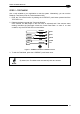
2.1.1 Indicators
The five LEDs on the side of the scanner (Figure A
) indicate the following:
READY
(green)
This LED indicates the device is ready to operate. For Subzero
models this LED blinks during the warm-up phase.
GOOD
(green)
This LED confirms successful reading.
TRIGGER
(yellow)
This LED indicates the status of the reading phase. *
COM
(yellow)
This LED indicates active communication on main serial port. **
STATUS
(red)
This LED indicates a NO READ result.
* In On-Line mode the TRIGGER LED corresponds to the active reading phase signaled by the Presence Sensor.
In Automatic and Continuous modes the TRIGGER LED is always on indicating that the reader is ready to read a
code.
** When connected to a Fieldbus network through the CBX500, the COM LED is always active, even in the
absence of data transmission, because of polling activity on the Fieldbus network.
During the reader startup (reset or restart phase), all the LEDs blink for one second.
On the back of the reader near the cable, the “POWER ON” LED indicates the laser scanner
is correctly powered.
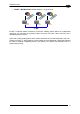
2.2 ID-NET™
The ID-NET™ is a built-in high-speed interface dedicated for high-
speed scanner interconnection. The ID-NET™ is in addition to the
Main and Auxiliary serial interfaces.
The following network configurations are available:
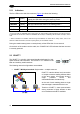
ID-NET™ M/S Synchronized: Single station – multiple scanners
CBX100
CBX100
CBX100
ID-NET™ interface allows local connection
of multiple scanners reading different sides
of the same target. All scanners share a
single presence sensor and
activate/deactivate simultaneously.
A
t the end of each reading phase a single
data message is transmitted to the host.
Thanks to ID-NET™, data communication
among scanners is highly efficient so that
an immediate result will be available.