
Installation manual


INSTALLATION
35
3
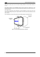
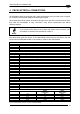
The reading distance of the scanner with the OM2000N is shifted by 10 mm towards the
scanner because of the internal optical path between the scanner and the OM2000N output
window. The reading performance also decreases in typical conditions by about 10% due to
the optical signal passing through the output window of the OM2000N and the reflection on
the mirror surface. The combination of these effects produces the reading diagram
represented below:
-10% READING FIELD
-10% READING FIELD
-10%
DOF
10
[0.39]
mm
in
Scanner Reading Diagram
without OM2000N
Scanner Reading Diagram
with OM2000N
Scanner Reading Diagram
shifted by 10 mm
Figure 31 – OM2000N Reading Performance Comparison
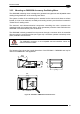
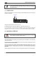
The reading distance also depends on the amplitude of aperture used. In particular, wider
apertures require the scanner to be closer to the code in order to read at the extreme edges
of the sweep (see Figure 32 below).
MAX. POSITION
MIN. POSITION
-35°
-15°
0°
+5°
77
[3.03]
23
[0.91]
Figure 32 – OM2000N Reading Distance
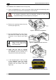
NOTE
The OM2000N is configurable exclusively through the Genius™ utility
program.
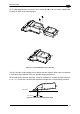
Fixed Position