
Installation manual


CBX ELECTRICAL CONNECTIONS
37
4
4 CBX ELECTRICAL CONNECTIONS
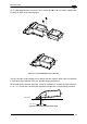
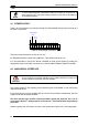
All DS2400N models are equipped with a cable terminated by a 25-pin male D-sub connector
for connection to the power supply and input/output signals.
We recommend making system connections through one of the CBX connection boxes since
they offer the advantages of easy connection, easy device replacement and filtered
reference signals.
NOTE
If you require direct wiring to the scanner the details of the connector pins
and relative connections are indicated in Chaper 5.
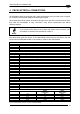
The table below gives the pinout of the CBX100/500 terminal block connectors. Use this
pinout when the DS2400N reader is connected by means of the CBX100/500:
CBX100/500 Terminal Block Connectors
Input Power
Vdc Power Supply Input Voltage +
GND Power Supply Input Voltage -
Earth Protection Earth Ground
Inputs
+V Power Source – External Trigger
I1A External Trigger A (polarity insensitive)
I1B External Trigger B (polarity insensitive)
-V Power Reference – External Trigger
+V Power Source – Inputs
I2A Input 2 A (polarity insensitive)
I2B Input 2 B (polarity insensitive)
-V Power Reference – Inputs
Outputs
+V Power Source - Outputs
-V Power Reference - Outputs
O1+ Output 1 +
O1- Output 1 -
O2+ Output 2 +
O2- Output 2 -
Auxiliary Interface
TX Auxiliary Interface TX
RX Auxiliary Interface RX
SGND Auxiliary Interface Reference
ID-NET™
REF Network Reference
ID+ ID-NET™ network +
ID- ID-NET™ network -
Shield Network Cable Shield
Main Interface
RS232
RS485
Full-Duplex
RS485
Half-Duplex
TX TX+ RTX+
RX
*RX+
RTS TX- RTX-
CTS
*RX-
SGND SGND SGND
* Do not leave floating, see par. 4.2.2 for connection details.