
Installation manual


DS2400N REFERENCE MANUAL
38
4
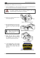
NOTE
To avoid electromagnetic interference when the scanner is connected to a
CBX connection box, verify the jumper positions in the CBX as indicated in
its Installation Manual.
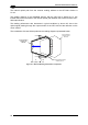
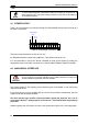
4.1 POWER SUPPLY
Power can be supplied to the scanner through the CBX100/500 spring clamp terminal pins
as shown in Figure 36:
V+
in
Earth
Ground
Power Supply
VGND
Figure 36 - Power Supply Connections
The power must be between 10 and 30 Vdc only.
For DS2400N Subzero models using CBX100 LT the power must be 24 Vdc.
It is recommended to connect the device CHASSIS to earth ground (Earth) by setting the
appropriate jumper in the CBX connection box. See the CBX Installation Manual for details.
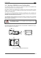
4.2 MAIN SERIAL INTERFACE
CAUTION
Do not connect to the Main Interface spring clamp terminals if using Host
Interface Modules (Fieldbus) with the CBX500.
The signals relative to the following serial interface types are available on the CBX spring
clamp terminal blocks.
If the interface type is not compatible with the current communication handshaking, then the
system forces the handshake to none.
The main interface type and the relative parameters (baud rate, data bits, etc.) can be
set using the Genius™ utility program or the Genius™ based Host Mode Programming
procedure.
Details regarding the connections and use of the interfaces are given in the next paragraphs.