
Installation manual


25-PIN CABLE ELECTRICAL CONNECTIONS
57
5
5.2.1 RS232 Interface
The serial interface is used in this case for point-to-point connections; it handles
communication with the host computer and allows both transmission of code data and the
programming of the scanner. This is the default setting.
The following pins are used for RS232 interface connection:
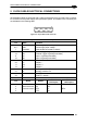
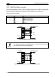
25-pin
Name Function
2 TX Transmit Data
3 RX Receive Data
4 RTS Request To Send
5 CTS Clear To Send
7 GND Ground
It is always advisable to use shielded cables. The overall maximum cable length must be
less than 15 m (49.2 ft).
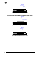
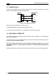
DS2400N
7
4
5
3
GND
RTS
CTS
RX
TX
2
USER INTERFACE
GND
CTS
RTS
TXD
RXD
1
Chassis
Figure 61 – RS232 Main Interface Connections Using Hardware Handshaking
The RTS and CTS signals control data transmission and synchronize the connected devices.
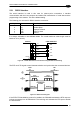
START
OF
TRANSMISSION
END
OF
TRANSMISSION
+ V
RTS
- V
+ V
TX DATA
- V
+ V
CTS
- V
DATA
TRANSMISSION
DATA
TRANSMISSION
C1
C2
C4
C3
C5
TRANSMISSION
STOPPED
ENABLED
DISABLED
ENABLED
IDLE
IDLE
Figure 62 - RS232 Control Signals
If the RTS/CTS handshaking protocol is enabled, the DS2400N activates the RTS output to
indicate a message is to be transmitted. The receiving unit activates the CTS input to enable
the transmission.