
Installation manual

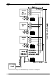

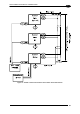
25-PIN CABLE ELECTRICAL CONNECTIONS
61
5
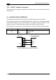
5.3 ID-NET™ INTERFACE
25-pin Name Function
23 ID+ ID-NET™ network +
24 ID- ID-NET™ network -
7 GND Ground
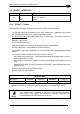
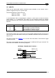
5.3.1 ID-NET™ Cables
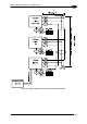
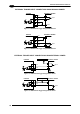
The following instructions are referred to Figure 68, Figure 69 and Figure 70.
The general cable type specifications are: CAT5 twisted pair + additional CAT5 twisted
pair, shielded cable AWG 24 (or AWG 22) stranded flexible.
We recommend using
DeviceNet cables (drop or trunk type) to the following reference
standards:
AN50325 – IEC 62026
UL STYLE 2502 80°C 30V
Cable Shield MUST be connected to earth ground ONLY at the Master.
NEVER use ID-NET™ cable shield as common reference.
The ID-NET™ max cable length depends on the baudrate used, (see the Baudrate Table
below).
For Common Power Connections use only 2 wires (23 and 24).
- DC Voltage Power cable (Vdc – GND) should be handled as a signal cable (i.e. do not
put it together with AC cable):
- Wire dimensioning must be checked in order to avoid voltage drops greater than 0.8
Volts.
- Cable should lie down as near as possible to the ID-NET™ cable (avoiding wide loops
between them).
Scanner's chassis may be connected to earth.
Network inside the same building.
Baudrate Table
Baud Rate 125 kbps 250 kbps
500 kbps
1Mbps
Cable Length 1200 m 900 m
700 m
*
* Application dependent, contact your Datalogic Automation representative for details.
NOTE
The default ID-NET™ baudrate is 500 kbps. Lower ID-NET™ baudrates
allow longer cable lengths. The baudrate is software configurable by
authorized Datalogic Automation personnel only.