
Installation manual

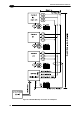

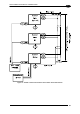
25-PIN CABLE ELECTRICAL CONNECTIONS
67
5
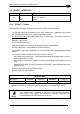
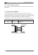
5.5 INPUTS
There are two optocoupled polarity insensitive inputs available on the scanner: Input 1
(External Trigger) and Input 2, a generic input:
The electrical features of both inputs are:
Maximum voltage: 30 Vdc
Maximum current: 12 mA
An anti-disturbance filter is implemented in software on both inputs so that the minimum
pulse duration is 5 milliseconds. This value can be increased through the software
parameter Debounce Filter, see the "2K/4K Family Software Configuration Parameter Guide”
Help file".
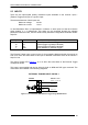
25-pin
Name Function
9 Vdc Power Source - External Trigger
18 I1A External Trigger A (polarity insensitive)
19 I1B External Trigger B (polarity insensitive)
7 GND Power Reference - External Trigger
The External Trigger input is used in the On-Line operating Mode and tells the scanner to
scan for a code. The active state of this input is selected in software. Refer to the Genius™
Help On Line.
The yellow Trigger LED (Figure A
, 3) is on when the active state of the External Trigger
corresponds to ON.
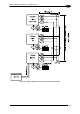
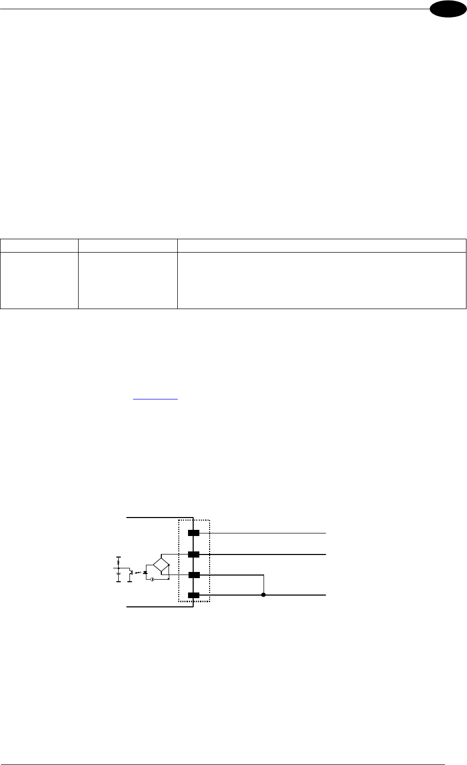
This input is optocoupled and can be driven by both an NPN and PNP type command. The
connections are indicated in the following diagrams:
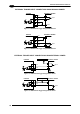
EXTERNAL TRIGGER INPUT PNP PH-1
Vdc
GND
I1A
I1B
PNP PH-1 wires
DS2400N
18
19
7
(brown) +10-30 Vdc
(black) NO
(blue) 0 V
V
CC
~
~
+
-
9
Figure 72 - PH-1 Photocell (PNP) External Trigger Using DS2400N Power