
Installation manual

TYPICAL LAYOUTS
83
6
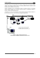
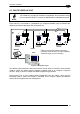
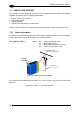
6.5 MULTIPLEXER LAYOUT
NOTE
This interface is provided for backward compatibility. We recommend using
the more efficient ID-NET™ network for Master/Slave or Multiplexer layouts.
Each scanner is connected to a Multiplexer (for example MX4000) with the RS485 half-
duplex main interface through a CBX connection box.
Figure 97 - Multiplexer Layout
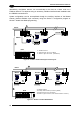
The auxiliary serial interface of the slave scanners can be used in Local Echo communication
mode to control any single scanner (visualize collected data) or to configure it using the
Genius™ utility or Genius™ based Host Mode programming procedure.
Each scanner has its own reading phase independent from the others. When On-Line
Operating mode is used, the scanner is activated by an External Trigger (photoelectric
sensor) when the object enters its reading zone.
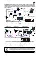
MX4000
Host
0
1
2
3
Main Serial Interface (RS485 Half-Duplex)
Auxiliary Serial Interface (Local Echo) (RS232)
External Trigger (for On-Line Mode)
1 31
3 3
2 2
Power