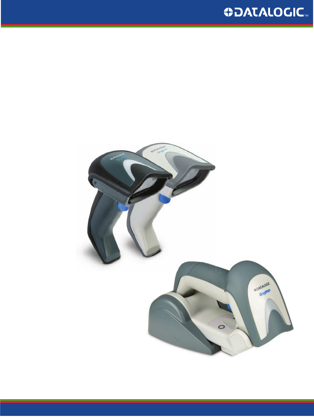
Gryphon™ 2D Family General Purpose Handheld Area Imager Bar Code Reader Gryphon I GD44XX/GBT4400/GM440X Product Reference Guide
Datalogic Scanning, Inc. 959 Terry Street Eugene, Oregon 97402 USA Telephone: (541) 683-5700 Fax: (541) 345-7140 An Unpublished Work - All rights reserved. No part of the contents of this documentation or the procedures described therein may be reproduced or transmitted in any form or by any means without prior written permission of Datalogic Scanning, Inc. or its subsidiaries or affiliates ("Datalogic" or “Datalogic Scanning”).
Table of Contents INTRODUCTION ................................................................................................................................................................................ 9 About this Manual .......................................................................................................................................................................................... 9 Overview ......................................................................................
Contents ACK Character ..................................................................................................................................................................................................................50 NAK Character ..................................................................................................................................................................................................................50 ACK NAK Timeout Value ...........................
Contents Motion Still Timeout ................................................................................................................................................................................................... 102 Flash On Time ................................................................................................................................................................................................................ 103 Flash Off Time ........................................
Contents Code 39 Quiet Zones .................................................................................................................................................................................................. 137 Code 39 Length Control ............................................................................................................................................................................................ 137 Code 39 Set Length 1 ...............................................
Contents Industrial 2 of 5 Set Length 2 ................................................................................................................................................................................... 167 CODE IATA ..................................................................................................................................................................................168 IATA Enable/Disable ............................................................................
Contents Plessey Set Length 1 ................................................................................................................................................................................................... 201 Plessey Set Length 2 ................................................................................................................................................................................................... 202 2D Symbologies..............................................
Contents Docking Beep ................................................................................................................................................................................................................ 239 Leash Alarm .................................................................................................................................................................................................................... 239 CONFIGURATION UPDATES ..........................
Contents BT-Only Features ............................................................................................................................................................................................................................... 288 Motion Features .........................................................................................................................................................................................289 Motionless Timeout ..................................
Chapter 1 Introduction About this Manual This Product Reference Guide (PRG) is provided for users seeking advanced technical information, including connection, programming, maintenance and specifications. The Quick Reference Guide (QRG) and other publications associated with this product are downloadable free of charge from the website listed on the back cover of this manual.
Introduction References Manual Conventions The following conventions are used in this document: The symbols listed below are used in this manual to notify the reader of key issues or procedures that must be observed when using the reader: Notes contain information necessary for properly diagnosing, repairing and operating the reader. The CAUTION symbol advises you of actions that could damage equipment or property.
About the Reader Introduction About the Reader Typically, units are factory-programmed for the most common terminal and communications settings. If you need to modify any programmable settings, custom configuration can be accomplished by scanning the programming bar codes within this guide. Two models of the Gryphon 2D are available, and are covered in this manual: • Gryphon I GD44XX - Corded 2D imager bar code reader • Gryphon I GBT4400 - Model with Bluetooth options.
Introduction The BC40xx™ Radio Base The BC40xx™ Radio Base Base LEDs LEDs on the Gryphon Base provide information about the Base’s status, as shown in Figure 1. Figure 1. Gryphon Base LEDs YELLOW LED BUTTON RED LED / GREEN LED The following table describes the significance of each LED: LED STATUS Yellow On = Base is powered Power on / Data Yellow Blinking = Base receives data and commands from the Host or the Reader. Charging Red On = Battery charging is in progress.
BC40XX UV Counterfeit Detection Introduction BC40XX UV Counterfeit Detection The BC40XX Radio Base is available with a UV Counterfeit Money Detector, typically used to verify the authenticity of bank notes. Other uses for counterfeit detection are passport, ticket, credit card, travelers’ check and similar applications where it is possible to detect fluorescent marks with UV light.
Introduction Battery Safety 3. The LEDs are set to switch off automatically after about 2 minutes. To keep the UV LEDs in always-on mode, quickly press the Base button a second time within 10 seconds of the first press. To switch them off, simply press the button again. An external power supply is necessary for full functionality of the Base station with UV Counterfeit Detector. Use only the recommended AC adapter 12Vdc.
Battery Safety Introduction Always charge the battery at 32° – 104°F (0° - 40°C) temperature range. CAUTION Use only the authorized power supplies, battery pack, chargers, and docks supplied by your Datalogic reseller. The use of any other power supplies can damage the device and void your warranty. Do not disassemble or modify the battery. The battery contains safety and protection devices, which, if damaged, may cause the battery to generate heat, explode or ignite.
Introduction Programming the Reader Programming the Reader Configuration Methods Programming Bar Codes The reader is factory-configured with a standard set of default features. After scanning the interface bar code, you can select other options and customize your reader through use of the instructions and programming bar code labels available in the corresponding features section for your interface. Customizable settings for many features are found in "Configuration Parameters" starting on page 37.
Chapter 2 Setup Unpacking Check carefully to ensure the reader and any accessories ordered are present and undamaged. If any damage occurred during shipment, contact Datalogic Technical Support. Information is shown on page 10. KEEP THE PACKAGING. Should the unit ever require service, it should be returned in its original shipping container.
Setup Installing the Interface Cable Installing the Interface Cable For Corded versions, connect the reader cable by inserting the cable into the handle as shown in Figure 2. To remove it, insert a paper clip into the release aperture, then unplug the cable. Figure 2. Connect/disconnect the cable RS-232 Serial Connection Turn off power to the terminal/PC and connect the reader to the terminal/PC serial port via the RS-232 cable as shown in Figure 3.
Installing the Interface Cable Setup Keyboard Wedge Connection The Keyboard Wedge cable has a ‘Y’ connection from the reader. Connect the female to the male end from the keyboard and the remaining end at the keyboard port at the terminal/PC. Reference Figure 4. Figure 4. Keyboard Wedge Interface connection USB Connection Connect the reader to a USB port on the terminal/PC using the correct USB cable for the interface type you ordered. Reference Figure 5. Figure 5.
Setup Configuring the Base Station nd Figure 6. Other Interface Connections W M Ke or... a IB W ybo ed ard ge or... Specific cables are required for connection to different hosts. The connectors illustrated above are examples only. Actual connectors may vary from those illustrated, but the steps to connect the reader remain the same. RF Models The power supply connects directly to the base (not on the cable's jack) for all configurations.
Configuring the Base Station Setup Changing the Base Station Position The base station is configured by installing one of two sets of mechanical parts that come with the cordless kit. The default mounts (shown below) provide three options: vertical (wall) mounting, standing (45°), or horizontal mounting with a higher mechanical retention of the scanner. Use the other mounts only for horizontal mounting, with lower retention of the scanner.
Setup Configuring the Base Station 3. The stand can now be repositioned in either horizontal or standing position. Horizontal Standing Connecting the Base Station Figure 7 shows how to connect the Base Station to a terminal, PC or other host device. Turn off the host before connection and consult the manual for that equipment (if necessary) before proceeding. Connect the interface cable before applying power to the Base Station.
Configuring the Base Station Setup Figure 7. Connecting the Base Station Wall plug Connector I/F Cable AC/DC Adapter DC Power Cord Base Station Securing the DC Power Cord (Optional) The DC power cord for the adapter can be secured to the bottom of the base in order to maximize the mechanical retention of the cable itself. The routing of the power cord can be changed to accommodate the base station positioning: horizontal, stand or wall mounting.
Setup Configuring the Base Station Figure 9. Arrows showing routing Host Connection: Verify before connection that the reader’s cable type is compatible with your host equipment. Most connections plug directly into the host device as shown in Figure 10. Keyboard Wedge interface cables have a ‘Y’ connection where its female end mates with the male end of the cable from the keyboard and the remaining end at the keyboard port on the terminal/PC. B Figure 10. Connecting to the Host Wa Ke W or...
Configuring the Base Station Setup Connecting the Base when Security Pin is Enabled When connecting the Base to a system that has a custom Security Pin enabled, follow the steps below in the order shown: 1. Power down the host system. 2. Connect the appropriate interface cable into the Base as shown in Figure 10. 3. Place the reader in the Base. 4. Power up the host. The reader will link to the Base 5.
Setup Configuring the Base Station Linking a BT Reader to a PC The reader can optionally be linked to a Bluetooth-enabled PC with the serial port profile, in either server mode or client mode. Linking to a PC in Server Mode (BT Slave Mode) To link a BT reader in server mode to a Bluetooth-enabled PC, follow these steps: 1. Install any drivers provided with the Bluetooth adapter. 2. Scan the bar code below to make the scanner visible to the host computer. ³ L n k S v Link to a PC in Server Mode 3.
Gryphon™ 2D System and Network Layouts Setup Gryphon™ 2D System and Network Layouts Stand Alone Layouts Figure 12. Single Reader Layout Figure 13. Multiple Reader Layout Wireless models only (not valid for BT model) In stand alone systems, each base station is connected to a single Host.
Setup Gryphon™ 2D System and Network Layouts Figure 14. Multiple Stand Alone Layouts Mobile models only (not valid for BT model) Many stand alone connections can operate in the same physical area without interference, provided all readers and base stations in the system have different addresses.
Interface Selection Setup Interface Selection Upon completing the physical connection between the reader and its host, proceed to Table 1 starting on page 30 to select the interface type the reader is connected to (for example: RS-232, Keyboard Wedge, USB, etc.). Scan the appropriate bar code in that section to configure your system’s correct interface type.
Setup Interface Selection Table 1.
Interface Selection Setup KEYBOARD FEATURES $P,HA2B,P(CR) USB Keyboard with alternate key encoding Select USB Alternate Keyboard $P,HA29,P(CR) AT, PS/2 25-286, 30-286, 50, 50Z, 60, 70, 80, 90 & 95 w/Standard Key Encoding Select KBD-AT $P,HA11,P(CR) Keyboard Wedge for IBM AT PS2 with standard key encoding but without external keyboard Select KBD-AT-NK $P,HA26,P(CR) AT, PS/2 25-286, 30-286, 50, 50Z, 60, 70, 80, 90 & 95 w/Alternate Key Select KBD-AT-ALT $P,HA10,P(CR) Keyboard Wedge for IBM AT PS2 with
Setup Interface Selection KEYBOARD — cont.
Customizing Configuration Settings Setup Customizing Configuration Settings Configure Interface Settings If after scanning the interface bar code from the previous table, your installation requires you to select options to further customize your reader, turn to the appropriate section for your interface type in "Configuration Parameters" starting on page 37.
Setup Customizing Configuration Settings Resetting the Product Configuration to Defaults Restore Custom Defaults If you aren’t sure what programming options are in your imager, or you’ve changed some options and want to restore the Custom Default Configuration that may have been saved in the scanner, scan the Restore Custom Default Configuration bar code below. This will restore the custom configuration for the currently active interface. Custom defaults are based on the interface type.
Customizing Configuration Settings Setup Replacing the Battery Before replacing the Battery, read "Battery Safety" starting on page 14. Datalogic recommends annual replacement of rechargeable battery packs to ensure maximum performance. To change the battery of your reader, complete the following instructions. 1. With a screwdriver, unscrew the battery cover screw. 2. Unscrew and remove the three screws securing the battery holder, and unplug the white connector. Connector Screw Screw 3.
Setup Customizing Configuration Settings 4. Remove the old battery from its place (if present), and insert the new battery in the same position. 5. Replace the battery holder and three screws, plug in the connector, and return the contacts circuit to its previous location. When inserting the new battery into the handle, take care to position the battery and the connector as shown. 6. Insert the cover in the handle and screw it back into place. Battery replacement is now complete.
Chapter 3 Configuration Using Bar Codes This and following sections provide programming bar codes to configure your reader by changing the default settings. For details about additional methods of programming, see "Configuration Methods" on page 16. You must first enable your reader to read bar codes in order to use this section. If you have not done this, go to Setup, starting on page 17 and complete the appropriate procedure.
Enter/Exit Programming Mode To program features: 1. Scan the ENTER/EXIT PROGRAMMING bar code, available at the top of each programming page, when applicable. 2. Scan the bar code to set the desired programming feature. You may need to cover unused bar codes on the page, and possibly the facing page, to ensure that the reader reads only the bar code you intend to scan. 3. If additional input parameters are needed, go to Appendix D, Keypad, and scan the appropriate characters from the keypad.
Global Interface Features Enter/Exit Programming Mode GLOBAL INTERFACE FEATURES The following interface features are configurable by all interface types. Host Commands — Obey/Ignore This option specifies whether the reader will obey or ignore host commands. When set to ignore, the reader will ignore all host commands except for those necessary for: • service mode • flash programming mode • keeping the interface active • transmission of labels.
Enter/Exit Programming Mode Global Interface Features NOTES 40 Gryphon™ I GD44XX/GBT4400/GM440X
RS-232 INTERFACE BAUD RATE on page 42 DATA BITS on page 43 STOP BITS on page 43 PARITY on page 44 HANDSHAKING CONTROL on page 45 Use the programming bar codes in this section if modifications to the standard RS-232 interface settings are necessary to meet your system’s requirements. Additional settings which apply to both the RS-232 and USB interfaces are available in the next section, "RS-232/USB-Com Interfaces" starting on page 46.
Enter/Exit Programming Mode RS-232 Interface Baud Rate See page 256 for information on this feature.
RS-232 Interface Enter/Exit Programming Mode Data Bits This parameter allows the reader to interface with devices requiring a 7-bit or 8-bit ASCII protocol for sending and receiving data. $CR2DA00(CR) 7 Data Bits $CR2DA01(CR) DEFAULT 8 Data Bits Stop Bits Set the number of stop bits to match host device requirements. See page 256 for more information on this feature.
Enter/Exit Programming Mode RS-232 Interface Parity This feature specifies parity required for sending and receiving data. Select the parity type according to host device requirements. See page 256 for more information.
RS-232 Interface Enter/Exit Programming Mode Handshaking Control See page 256 for more information about this feature.
RS-232/USB-COM INTERFACES INTERCHARACTER DELAY on page 47 BEEP ON ASCII BEL on page 47 BEEP ON NOT ON FILE on page 48 ACK NAK OPTIONS on page 49 ACK CHARACTER on page 50 NAK CHARACTER on page 50 ACK NAK TIMEOUT VALUE on page 51 ACK NAK RETRY COUNT on page 51 ACK NAK ERROR HANDLING on page 52 INDICATE TRANSMISSION FAILURE on page 52 DISABLE CHARACTER on page 53 ENABLE CHARACTER on page 53 The programming bar codes in this chapter allow modifications to the standard RS-232 and USB-Com interfaces.
RS-232/USB-Com Interfaces Enter/Exit Programming Mode Intercharacter Delay This parameter specifies the intercharacter delay between the end of one character and the beginning of the next. The delay can be set within a range of zero (0) to 990 milliseconds in 10ms increments. A setting of zero specifies no delay. See page 265 for more information.
Enter/Exit Programming Mode RS-232/USB-Com Interfaces Beep On Not on File This option enables/disables the action of the reader to sound a three beep sequence upon receiving a Not-On-File (NOF) host command.
RS-232/USB-Com Interfaces Enter/Exit Programming Mode ACK NAK Options This enables/disables the ability of the reader to support the RS-232 ACK/NAK protocol. See page 258 for more information.
Enter/Exit Programming Mode RS-232/USB-Com Interfaces ACK Character This setting specifies an ASCII character or hex value to be used as the ACK character. ASCII characters or any hex value from 0 to 0xFF can be selected. See page 258 for more information. Setting to previously defined characters such as XON, XOFF, or host commands conflicts with normal operation of these characters. 8-bit data is not recognized when the option Data Bits has been set as 7 Data Bits.
RS-232/USB-Com Interfaces Enter/Exit Programming Mode ACK NAK Timeout Value This option specifies the amount of time the reader waits for an ACK character from the host following label transmission. The selectable timeout range is 200 milliseconds to 15,000ms (15 seconds) in 200ms increments. A selection of 0 disables the timeout. See page 260 for more information on setting this feature.
Enter/Exit Programming Mode RS-232/USB-Com Interfaces ACK NAK Error Handling This feature specifies the method the reader uses to handle receive errors detected while waiting for an ACK character from the host.
RS-232/USB-Com Interfaces Enter/Exit Programming Mode Disable Character Specifies the value of the RS-232 host command used to disable the reader. ASCII characters or any hex value from 0 to 0xFF can be selected. Setting to previously defined characters such as XON, XOFF, or host commands conflicts with normal operation of these characters. 8-bit data is not recognized when the option Data Bits has been set as 7 Data Bits. See page 262 for more information on setting this feature.
Enter/Exit Programming Mode RS-232/USB-Com Interfaces NOTES 54 Gryphon™ I GD44XX/GBT4400/GM440X
KEYBOARD SETTINGS COUNTRY MODE on page 56 SEND CONTROL CHARACTERS on page 60 WEDGE QUIET INTERVAL on page 61 INTERCODE DELAY on page 61 CAPS LOCK STATE on page 62 NUMLOCK on page 62 USB KEYBOARD SPEED on page 63 USB KEYBOARD NUMERIC KEYPAD on page 64 Use the programming bar codes in this chapter to select options for USB Keyboard and Wedge Interfaces. Reference Appendix B, Standard Defaults for a listing of standard factory settings.
Enter/Exit Programming Mode Keyboard Settings Country Mode This feature specifies the country/language supported by the keyboard. Several languages are supported: $CKBCO00(CR) DEFAULT Country Mode = U.S. $CKBCO01(CR) Country Mode = Belgium $CKBCO02(CR) Country Mode = Britain $CKBCO11(CR) Supports only the interfaces listed in the Country Mode feature description. Country Mode = Croatia $CKBCO0E(CR) Supports only the interfaces listed in the Country Mode feature description.
Keyboard Settings Enter/Exit Programming Mode Country Mode (Continued) $CKBCO04(CR) Country Mode = France $CKBCO13(CR) Supports only the interfaces listed in the Country Mode feature description. Country Mode = French Canadian $CKBCO05(CR) Country Mode = Germany $CKBCO0D(CR) Supports only the interfaces listed in the Country Mode feature description. Country Mode = Hungary $CKBCO06(CR) Country Mode = Italy $CKBCO0C(CR) Supports only the interfaces listed in the Country Mode feature description.
Enter/Exit Programming Mode Keyboard Settings Country Mode (Continued) $CKBCO14(CR) Supports only the interfaces listed in the Country Mode feature description. Country Mode = Lithuanian $CKBCO07(CR) Country Mode = Norway $CKBCO12(CR) Supports only the interfaces listed in the Country Mode feature description. Country Mode = Poland $CKBCO08(CR) Supports only the interfaces listed in the Country Mode feature description.
Keyboard Settings Enter/Exit Programming Mode $CKBCO09(CR) Country Mode = Spain $KBCO0A(CR) Country Mode = Sweden $CKBCO0B(CR) Supports only the interfaces listed in the Country Mode feature description.
Enter/Exit Programming Mode Keyboard Settings Send Control Characters This feature specifies how the reader transmits ASCII control characters to the host. Reference Appendix E, Scancode Tables for more information about control characters. Options are as follows: Control Character 00 : Characters from 00 to 0x1F are sent as control character Ctrl+Keys, special keys are located from 0x80 to 0xA1.
Keyboard Settings Enter/Exit Programming Mode Wedge Quiet Interval Specifies amount of time to look for keyboard activity before scanner breaks keyboard connection in order to transmit data to host. The selectable range for this setting is 00 to 990 milliseconds (00-0x63 by 01) in increments of ten milliseconds. See page 264 in “References” for detailed information and examples for setting this feature.
Enter/Exit Programming Mode Keyboard Settings Caps Lock State This option specifies the format in which the reader sends character data. This does not apply when an alternate key encoding keyboard is selected. $CKBCL00(CR) DEFAULT Caps Lock State = Caps Lock OFF $CKBCL01(CR) Caps Lock State = Caps Lock ON $CKBCL02(CR) Caps Lock State = AUTO Caps Lock Enable Numlock This option specifies the setting of the NUMLOCK key in the Keyboard Wedge interface.
Keyboard Settings Enter/Exit Programming Mode USB Keyboard Speed This option specifies the USB poll rate for a USB keyboard. This feature applies ONLY to the USB Keyboard interface.
Enter/Exit Programming Mode Keyboard Settings USB Keyboard Speed — continued $CKBSP07(CR) USB Keyboard Speed = 7ms $CKBSP08(CR) USB Keyboard Speed = 8ms $CKBSP09(CR) USB Keyboard Speed = 9ms $CKBSP0A(CR) USB Keyboard Speed = 10ms USB Keyboard Numeric Keypad This option Controls whether numeric characters will be sent using standard keys or the numeric keypad.
USB-OEM INTERFACE USB-OEM DEVICE USAGE on page 66 INTERFACE OPTIONS on page 66 Feature settings for USB interfaces differ depending upon which host type the reader will be connected with. Use the feature settings in this chapter and "IBM 46XX Interface" on page 67 to specifically configure for the USB-OEM interface. Other USB interfaces are included in the appropriate chapter for their host type. Reference Appendix B for a listing of standard factory settings.
Enter/Exit Programming Mode USB-OEM Interface USB-OEM Device Usage The USB-OEM protocol allows for the reader to be identified as one of two different types of bar code scanners. Depending on what other scanners you may already have connected to a USB-OEM POS, you may need to change this setting to enable all devices to communicate. Options are: • Table Top Scanner • Handheld Scanner It may be necessary to switch device usage when connecting two readers/scanners of the same type to a POS system.
IBM 46XX INTERFACE 46XX NUMBER OF HOST RESETS on page 68 TRANSMIT LABELS IN CODE 39 FORMAT on page 70 INTERFACE OPTIONS on page 70 Use the bar codes in this section to configure programmable features for available IBM 46XX interfaces. Reference Appendix B for a listing of standard factory settings.
Enter/Exit Programming Mode IBM 46XX Interface 46xx Number of Host Resets Specifies how many consecutive resets are processed before the reader starts a five-second period to allow the user to enter Programming Mode and configure the reader. The configurable range for this feature is 1 to 15 resets.
IBM 46XX Interface Enter/Exit Programming Mode 46xx Number of Host Resets — cont.
Enter/Exit Programming Mode IBM 46XX Interface Transmit Labels in Code 39 Format This feature enable/disables translation to Code 39 before transmitting label data to an IBM46XX or a USB-OEM host. Only the symbology identifier is modified for the translation. The data is not converted to Code 39 or verified to be valid for Code 39. Options are: IBM Standard Format: Send labels in standard IBM format.
WAND EMULATION INTERFACE This feature is valid only for the GBT4400 model. WAND SIGNAL SPEED on page 72 WAND POLARITY on page 72 WAND IDLE STATE on page 73 TRANSMIT NOISE on page 73 LABEL SYMBOLOGY CONVERSION on page 74 This chapter provides feature/settings configuration for the Wand Emulation interface. Reference Appendix B for a listing of standard factory settings.
Enter/Exit Programming Mode Wand Emulation Interface Wand Signal Speed This feature specifies the speed of the Wand output signal per nominal bar or space. Choices are: • 330 microseconds • 660 microseconds $CWASP00(CR) Wand Signal Speed = 330ms $CWASP01(CR) DEFAULT Wand Signal Speed = 660ms Wand Polarity This option specifies the polarity of the Wand output signal.
Wand Emulation Interface Enter/Exit Programming Mode Wand Idle State This feature specifies the level of the Wand output signal when the reader is idle. TTL logic levels: 0V <= Low <= 0.7V 2.4V <= High <= 5.25V $CWAID00(CR) Wand Idle State = Low $CWAID01(CR) DEFAULT Wand Idle State = High Transmit Noise This option specifies the leading/trailing noise for the Wand interface.
Enter/Exit Programming Mode Wand Emulation Interface Label Symbology Conversion When this feature is enabled for the Wand Emulation interface, all bar code labels are converted to a single symbology.
DATA FORMAT GLOBAL PREFIX/SUFFIX starting on page 76 GLOBAL AIM ID starting on page 77 LABEL ID starting on page 80 •Label ID: Pre-Loaded Sets •Individually Set Label ID •Label ID Control •Label ID Symbology Selection •Label ID Symbology Selection • 1D Symbologies • 2D Symbologies CASE CONVERSION starting on page 87 CHARACTER CONVERSION starting on page 88 It is not recommended to use these features with IBM interfaces.
Enter/Exit Programming Mode Global Prefix/Suffix Global Prefix/Suffix This option sets up to 20 characters each from the set of ASCII characters or any hex value from 00 to FF. The characters may be added as a prefix (in a position before the bar code data, also called a header) and/or as a suffix (in a position following the bar code data, also called a footer). See page 269 for more detailed instructions on setting this feature.
Global AIM ID Enter/Exit Programming Mode Global AIM ID This feature enables/disables addition of AIM IDs for all symbology types. AIM label identifiers (as opposed to custom characters you select yourself as with label identifiers) can be included with scanned bar code data. See Table 2 on page 3-77 for a listing of AIM IDs. AIM label identifiers consist of three characters as follows: • A close brace character (ASCII ‘]’), followed by...
Enter/Exit Programming Mode DATABAR EXPANDED COMPOSITE DATABAR LIMITED DATABAR LIMITED COMPOSITE DATA MATRIX EAN128 EAN128 COMPOSITE EAN13 EAN13 P2 EAN13 P5 EAN13 COMPOSITE EAN8 EAN8 P2 EAN8 P5 EAN8 COMPOSITE FOLLET 2OF5 I2OF5 IATA INDUSTRIAL 2OF5 INDUSTRIAL 2OF5 ISBN ISBT128 CONCAT ISSN MAXICODE MICRO QR MICRO PDF MSI PDF417 PLESSEY POSTAL AUSTRALIAN POSTAL IMB POSTAL JAPANESE POSTAL KIX POSTAL PLANET POSTAL PORTUGAL POSTAL POSTNET BB POSTAL ROYAL MAIL POSTAL SWEDISH POSTNET QR CODE S25 TRIOPTIC UPCA UPCA
Global AIM ID Enter/Exit Programming Mode Set AIM ID Individually for GS1-128 This feature configures a Label ID individually for the GS1-128 symbology and the programming for this works the same way as Label ID. See Label ID: Set Individually Per Symbology, starting on page 274 for detailed instructions on setting this feature.
Enter/Exit Programming Mode Label ID Label ID A Label ID is a customizable code of up to three ASCII characters (convert to Hex using the ASCII Chart on the inside back cover of this manual), used to identify a bar code symbology type. It can be appended previous to or following the transmitted bar code data depending upon how this option is enabled. This feature provides options for configuring custom Label IDs or individually per symbology (see "Individually Set Label ID" on page 81).
Label ID Enter/Exit Programming Mode Individually Set Label ID This feature configures a Label ID individually for a single symbology. To set, first define whether you want it as a prefix or suffix by scanning a label below. Then turn to Label ID Symbology Selection • 1D Symbologies, starting on page 82 to select the symbology you want to set, followed by up to 3 characters from the ASCII Chart at the back of this manual.
Enter/Exit Programming Mode Label ID Label ID Symbology Selection − 1D Symbologies This option selects the symbology for which a Label ID is to be configured. See "Label ID" on page 80 or page 274 in “References” for more detailed instructions. If less than the expected string of 3 characters are selected, scan the ENTER/ EXIT bar code twice to accept the selection and exit Programming Mode.
Label ID Enter/Exit Programming Mode Label ID Symbology Selection − 1D Symbologies (continued) $CCCID Set Code 39 CIP Label ID Character(s) $C8BID Set EAN 8 Label ID Character(s) $C8MID Set EAN 8 Composite Label ID Character(s) $C82ID Set EAN 8 P2 Label ID Character(s) $C85ID Set EAN 8 P5 Label ID Character(s) $CF2ID Set Follett 2 of 5 Label ID Character(s) $C4BID Set GS1 DataBar 14 Label ID Character(s) $C4CID Set GS1 DataBar 14 Composite Label ID Character(s) Product Reference Guide $C35ID
Enter/Exit Programming Mode Label ID Label ID Symbology Selection − 1D Symbologies (continued) $CXBID Set GS1 DataBar Expanded Label ID Character(s) $CIAID Set IATA Industrial 2 of 5 Label ID Character(s) $CPMID Set IMB Postal Code Label ID Character(s) $CU2ID Set Industrial 2 of 5 Label ID Character(s) $CI2ID Set Interleaved 2 of 5 Label ID Character(s) $CISID Set ISBN Label ID Character(s) $CINID Set ISSN Label ID Character(s) $CPJID Set Japan Postal Code Label ID Character(s) 84 $CGBID Set
Label ID Enter/Exit Programming Mode Label ID Symbology Selection − 1D Symbologies (continued) $CPZID Set PZN Code Label ID Character(s) $CPBID Set Postnet BB Label ID Character(s) $CPRID $CAMID Set Royal Postal Code Label ID Character(s) Set UPC-A Composite Label ID Character(s) $CS2ID $CA2ID Set Standard 2 of 5 Label ID Character(s) $CPSID Set Swedish Postal Code Label ID Character(s) $CCTID Set Trioptic Code Label ID Character(s) $CABID Set UPC-A Label ID Character(s) Product Reference Gu
Enter/Exit Programming Mode Label ID Label ID Symbology Selection − 2D Symbologies $CAZID Set Aztec Label ID Character(s) $CCSID Set China Sensible Label ID Character(s) $CDMID Set Data Matrix Label ID Character(s) $CMQID Set Micro QR Label ID Character(s) 86 $CMXID Set Maxicode Label ID Character(s) $CP4ID Set PDF 417 Label ID Character(s) $CMIID Set Micro PDF 417 Label ID Character(s) $CQRID Set QR Code Label ID Character(s) Gryphon™ I GD44XX/GBT4400/GM440X
Label ID Enter/Exit Programming Mode Advanced Formatting: User Label Edit Advanced formatting is available to create user label edit scripts. See the Datalogic Aladdin configuration application or contact Technical Support. Case Conversion This feature allows conversion of the case of all alphabetic characters to upper or lower case. Case conversion affects ONLY scanned bar code data, and does not affect Label ID, Prefix, Suffix, or other appended data.
Enter/Exit Programming Mode Label ID Character Conversion Character conversion is an eight byte configuration item. The eight bytes are 4 character pairs represented in hexadecimal ASCII values. The first character in the pair is the character that will be converted. The second character in the pair is the character to convert to. If the character to convert in a pair is FF, then no conversion is done.
READING PARAMETERS DOUBLE READ TIMEOUT starting on page 90 LED AND BEEPER INDICATORS starting on page 92 •Power On Alert •Good Read: When to Indicate •Good Read Beep Type •Good Read Beep Frequency •Good Read Beep Length •Good Read Beep Volume •Good Read LED Duration SCANNING FEATURES starting on page 97 •Scan Mode •Stand Mode Indication •Stand Operation •Pick Mode •Stand Mode Sensitivity •Stand Mode Illumination Off Time •Scanning Active Time •Stand Illumination Control •Flash On Time •Flash Off Time •Aimi
Enter/Exit Programming Mode Reading Parameters Double Read Timeout Double Read Timeout prevents a double read of the same label by setting the minimum time allowed between reads of labels of the same symbology and data. If the unit reads a label and sees the same label again within the specified timeout, the second read is ignored. Double Read Timeout does not apply to scan modes that require a trigger pull for each label read. $CSNDR0A(CR) Double Read Timeout = 0.
Reading Parameters Enter/Exit Programming Mode Double Read Timeout — continued $CSNDR50(CR) Double Read Timeout = 0.8 Second $CSNDR5A(CR) Double Read Timeout = 0.
Enter/Exit Programming Mode Reading Parameters LED AND BEEPER INDICATORS Power On Alert Disables or enables the indication (from the Beeper) that the reader is receiving power. $CBPPU00(CR) Power On Alert = Disable (No Audible Indication) $CBPPU01(CR) DEFAULT Power On Alert = Power-up Beep Good Read: When to Indicate This feature specifies when the reader will provide indication (beep and/or flash its green LED) upon successfully reading a bar code.
Reading Parameters Enter/Exit Programming Mode Good Read Beep Type Specifies whether the good read beep has a mono or bitonal beep sound. $CBPTY00(CR) DEFAULT Good Read Beep Type = Mono $CBPTY01(CR) Good Read Beep Type = Bitonal Good Read Beep Frequency Adjusts the good read beep to sound at a selectable low, medium or high frequency, selectable from the list below. (Controls the beeper’s pitch/tone.
Enter/Exit Programming Mode Reading Parameters Good Read Beep Length $CBPLE06(CR) Good Read Beep Length = 60 msec $CBPLE08(CR) DEFAULT Good Read Beep Length = 80 msec $CBPLE0A(CR) Good Read Beep Length = 100 msec $CBPLE0C(CR) Good Read Beep Length = 120 msec $CBPLE0E(CR) Good Read Beep Length = 140 msec $CBPLE10(CR) Good Read Beep Length = 160 msec $CBPLE12(CR) Good Read Beep Length = 180 msec $CBPLE14(CR) Good Read Beep Length = 200 msec 94 Gryphon™ I GD44XX/GBT4400/GM440X
Reading Parameters Enter/Exit Programming Mode Good Read Beep Volume Selects the beeper volume (loudness) upon a good read beep. There are three selectable volume levels.
Enter/Exit Programming Mode Reading Parameters Good Read LED Duration This feature specifies the amount of time that the Good Read LED remains on following a good read. The good read LED on time can be set within a range of 100 milliseconds to 25,500 milliseconds (0.1 to 25.5 seconds) in 100ms increments. A setting of 00 keeps the LED on until the next trigger pull. See page 277 in “References” for detailed instructions and examples for setting this feature.
Reading Parameters Enter/Exit Programming Mode SCANNING FEATURES Scan Mode Selects the reader’s scan operating mode. See page 278 in “References” for descriptions.
Enter/Exit Programming Mode Reading Parameters Stand Mode Indication This operation is useful for indicating when the reader is in Stand Mode. If enabled, the blue indicator will blink when Stand Mode scanning is active. If reader detects motion (or removed from base station for cordless models) and switches out of Stand Mode into Triggered Mode, blinking will stop until Stand Mode is active again.
Reading Parameters Enter/Exit Programming Mode Stand Operation Specifies the behavior of the reader when stationary in a stand. There are two conditions which cause the reader to switch to Stand Mode: 1. The reader is configured to switch to Stand Mode when stationary. 2. The reader is placed into the cradle of the base station. Below are further options concerning Stand Operation. Ignore Autorecognition. Disables mode switching when the reader is placed in a stand. Switch to Stand Mode.
Enter/Exit Programming Mode Reading Parameters Pick Mode Specifies the ability of the reader to decode labels only when they are close to the center of the aiming pattern. This allows the reader to accurately target labels when they are placed close together, such as on a pick sheet. This feature is not compatible with Multiple Labels Reading in a Volume. $CSNPM00(CR) DEFAULT Pick Mode = Disable $CSNPM01(CR) Pick Mode = Enable Stand Mode Sensitivity Sets the sensitivity level for stand mode wakeup.
Reading Parameters Enter/Exit Programming Mode Stand Mode Illumination Off Time Specifies the amount of time reader illumination stays off after pulling the trigger when in Stand Mode. The configurable range is 01 to 32 by 01 in increments of 500ms (500ms to 16 seconds). See page 279 in “References” for a description of this feature.
Enter/Exit Programming Mode Reading Parameters Stand Illumination Control Controls the illumination status while the reading mode is stand mode and the reader is attempting to detect objects. $CSMIL00(CR) DEFAULT Stand Illumination Control = OFF $CSMIL01(CR) Stand Illumination Control = ON $CSMIL02(CR) Stand Illumination Control = Dim Motion Still Timeout Motion Still Timeout specifies the waiting time after which no motions is detected.
Reading Parameters Enter/Exit Programming Mode Flash On Time This feature specifies the ON time for the indicator LED while in Flash Mode. The selectable range is 100 to 9,900 milliseconds (0.1 to 9.9 seconds), in 100 millisecond increments. See page 282 in “References” for detailed information on setting this feature.
Enter/Exit Programming Mode Reading Parameters Aiming Pointer Enables/disables the aiming pointer for all symbologies. $CTAAP00(CR) Aiming Pointer = Disable $CTAAP01(CR) DEFAULT Aiming Pointer = Enable Aiming Duration Timer Specifies the frame of time the aiming pointer remains on after decoding a label, when in trigger single mode.The range for this setting is from 1 to 255 seconds in 1-second increments. See page 281 in “References” for a description of this feature.
Reading Parameters Enter/Exit Programming Mode Green Spot Duration Specifies the duration of the good read pointer beam after a good read. $CLSSP00(CR) Green Spot Duration = Disable (Green Spot is Off ) $CLSSP01(CR) DEFAULT Green Spot Duration = Short (300 msec) $CLSSP02(CR) Green Spot Duration = Medium (500 msec) $CLSSP03(CR) Green Spot Duration = Long (800 msec) Mobile Phone Mode This mode is useful for scanning bar codes displayed on a mobile phone.
Enter/Exit Programming Mode Reading Parameters Partial Label Reading Control Enable/Disable to ignore partial labels to be read within the boundary of the field of view. IPPL00 Partial Label Reading Control = Disable IPPL01 Partial Label Reading Control = Enable Decode Negative Image Enable/Disable the ability to decode a negative image for all symbologies. When this feature is enabled, you will be unable to read normally-printed labels or programming labels in this manual.
Reading Parameters Enter/Exit Programming Mode CORDED ONLY FEATURES Corded Stand Mode Sets the Stand Mode Operation for Corded models This feature is available starting with firmware release 610001013.
Enter/Exit Programming Mode Reading Parameters Corded Stand Beep Enables/Disables the beep that indicates when Corded Stand position is detected. This feature is available starting on firmware release 610001013.
Reading Parameters MULTIPLE LABEL READING In standard (default) mode, when the reader’s aiming system is activated (by a trigger pull, motion or other method depending on the mode), it then acquires and processes each image in the area in front of it (the Volume). In this case, the scanner stops processing the image once it decodes a label. If several labels are present in the volume, only the first label encountered is decoded and sent.
Multiple Labels Ordering by Code Symbology This feature allows you to specify the order multiple labels are transmitted by symbology type, when Multiple Labels per Frame is enabled. See page 284 in “References” for detailed information on setting this feature. $CSNMS Select Symbologies for Multiple Labels Ordering Make a mistake? Scan the CANCEL bar code to abort and not save the entry string. You can then start again at the beginning.
1D SYMBOLOGIES 1D Code Selection The reader supports the following 1D symbologies (bar code types). See "2D Symbologies" starting on page 203 for 2D bar codes. Symbology-dependent options are included in each chapter.
Enter/Exit Programming Mode Disable All Symbologies 4. Complete the programming sequence by scanning the ENTER/EXIT PROGRAMMING bar code to exit Programming Mode. DISABLE ALL SYMBOLOGIES Use this feature to disable all symbologies. 1. Scan the ENTER/EXIT PROGRAMMING Mode bar code. 2. Scan the Disable All Symbologies bar code. 3. Complete the programming sequence by scanning the ENTER/EXIT PROGRAMMING bar code. $AD(CR) Disable All Symbologies This does not disable the reading of programming labels.
Code EAN/UPC Enter/Exit Programming Mode CODE EAN/UPC Coupon Control This feature is used to control the reader’s method of processing coupon labels.
Enter/Exit Programming Mode Code EAN/UPC UPC-A The following options apply to the UPC-A symbology. UPC-A Enable/Disable When disabled, the reader will not read UPC-A bar codes. $CABEN00(CR) UPC-A = Disable $CABEN01(CR) DEFAULT UPC-A = Enable UPC-A Check Character Transmission Enable this option to transmit the check character along with UPC-A bar code data.
Code EAN/UPC Enter/Exit Programming Mode Expand UPC-A to EAN-13 Expands UPC-A data to the EAN-13 data format. Selecting this feature also changes the symbology ID to match those required for EAN-13. $CAB3B00(CR) DEFAULT UPC-A to EAN-13 = Don’t Expand $CAB3B01(CR) UPC-A to EAN-13 = Expand UPC-A Number System Character Transmission This feature enables/disables transmission of the UPC-A number system character.
Enter/Exit Programming Mode UPC-E UPC-A 2D Component This feature enables/disables a requirement that a 2D label component be decoded when a base label of this symbology is decoded. $CAB2D00(CR) DEFAULT EAN-13 2D Component = Disable (2D component not required) $CAB2D01(CR) EAN-13 2D Component = 2D component must be decoded UPC-E The following options apply to the UPC-E symbology. UPC-E Enable/Disable When disabled, the reader will not read UPC-E bar codes.
UPC-E Enter/Exit Programming Mode UPC-E Check Character Transmission Enable this option to transmit the check character along with UPC-E bar code data. $CEBCT00(CR) UPC-E Check Character Transmission = Don’t Send $CEBCT01(CR) DEFAULT UPC-E Check Character Transmission = Send UPC-E 2D Component This feature enables/disables a requirement that a 2D label component be decoded when a base label for this symbology is decoded.
Enter/Exit Programming Mode UPC-E Expand UPC-E to EAN-13 Expands UPC-E data to the EAN-13 data format. Selecting this feature also changes the symbology ID to match those required for EAN-13. $CEB3B00(CR) DEFAULT UPC-E to EAN-13 = Don’t Expand $CEB3B01(CR) UPC-E to EAN-13 = Expand Expand UPC-E to UPC-A Expands UPC-E data to the UPC-A data format.
GTIN Formatting Enter/Exit Programming Mode UPC-E Number System Character Transmission This feature enables/disables transmission of the UPC-E system number character. $CEBNS00(CR) UPC-E Number System Character = Do not transmit $CEBNS01(CR) DEFAULT UPC-E Number System Character = Transmit GTIN FORMATTING This feature enables/disables the ability to convert UPC-E, UPC-A, EAN 8, and EAN 13 labels into the GTIN 14-character format.
Enter/Exit Programming Mode EAN 13 (Jan 13) EAN 13 (JAN 13) The following options apply to the EAN 13 (Jan 13) symbology. EAN 13 Enable/Disable When disabled, the reader will not read EAN 13/JAN 13 bar codes. $C3BEN00(CR) EAN 13 = Disable $C3BEN01(CR) DEFAULT EAN 13 = Enable EAN 13 Check Character Transmission Enable this option to transmit the check character along with EAN 13 bar code data.
EAN 13 (Jan 13) Enter/Exit Programming Mode EAN-13 Flag 1 Character Enables/disables transmission of an EAN/JAN13 Flag1 character. The Flag 1 character is the first character of the label. $C3BF100(CR) EAN-13 Flag 1 Char= Don’t transmit $C3BF101(CR) DEFAULT EAN-13 Flag 1 Char= Transmit EAN-13 ISBN Conversion This option enables/disables conversion of EAN 13/JAN 13 Bookland labels starting with 978 to ISBN labels.
Enter/Exit Programming Mode ISSN EAN-13 2D Component This feature enables/disables a requirement that a 2D label component be decoded when a base label of this symbology is decoded. $C3B2D00(CR) DEFAULT EAN-13 2D Component = Disable (2D component not required) $C3B2D01(CR) EAN-13 2D Component = 2D component must be decoded ISSN The following options apply to the ISSN symbology. ISSN Enable/Disable Enables/disables conversion of EAN/JAN13 Bookland labels starting with 977 to ISSN labels.
EAN 8 (Jan 8) Enter/Exit Programming Mode EAN 8 (JAN 8) The following options apply to the EAN 8 (Jan 8) symbology. EAN 8 Enable/Disable When disabled, the reader will not read EAN 8/JAN 8 bar codes. $C8BEN00(CR) EAN 8 = Disable $C8BEN01(CR) DEFAULT EAN 8 = Enable EAN 8 Check Character Transmission Enable this option to transmit the check character along with EAN 8 bar code data.
Enter/Exit Programming Mode EAN 8 (Jan 8) Expand EAN 8 to EAN 13 Enable this option to expand EAN 8/JAN 8 labels to EAN 13/JAN 13. $C8B3B00(CR) DEFAULT Expand EAN 8 to EAN 13 = Disable $C8B3B01(CR) Expand EAN 8 to EAN 13 = Enable EAN 8 2D Component This feature enables/disables a requirement that a 2D label component be decoded when a base label for this symbology is decoded.
UPC/EAN Global Settings Enter/Exit Programming Mode UPC/EAN GLOBAL SETTINGS This section provides configuration settings for UPC-A, UPC-E, EAN 13 and EAN 8 symbologies, and affects all of these unless otherwise marked for each feature description. UPC/EAN Price Weight Check This feature enables/disables calculation and verification of price/weight check digits.
Enter/Exit Programming Mode UPC/EAN Global Settings UPC/EAN Quiet Zones This feature specifies the number of quiet zones for UPC/EAN labels. Quiet zones are blank areas at the ends of a bar code, typically 10 times the width of the narrowest bar or space in the label. The property applies to all EAN-UPC symbologies globally and to the ADDONs.
Add-Ons Enter/Exit Programming Mode ADD-ONS Contact Customer Support for advanced programming of optional and conditional add-ons. Optional Add-ons The reader can be enabled to optionally read the following add-ons (supplementals): If a UPC/EAN base label and an add-on are both decoded, the reader will transmit the base label and add-on. If a UPC/EAN base label is decoded without an add-on, the base label will be transmitted without an add-on.
Enter/Exit Programming Mode Add-Ons Optional Add-On Timer This option sets the time the reader will look for an add-on when an add-on fragment has been seen and optional add-ons are enabled. (Also see "Optional GS1-128 Add-On Timer" on page 131.
Add-Ons Enter/Exit Programming Mode Optional Add-On Timer — cont.
Enter/Exit Programming Mode Add-Ons Optional Add-On Timer — cont.
Add-Ons Enter/Exit Programming Mode Optional GS1-128 Add-On Timer This option sets the timer expiration value to read the added part after reading the linear EAN/ UPC part. For UPC/EAN add-ons other than those of that type, see "Optional Add-On Timer" on page 128.
Enter/Exit Programming Mode Add-Ons Optional GS1-128 Add-On Timer — cont.
Add-Ons Enter/Exit Programming Mode Optional GS1-128 Add-On Timer — cont.
Enter/Exit Programming Mode Code 39 CODE 39 The following options apply to the Code 39 symbology. Code 39 Enable/Disable $CC3EN00(CR) Code 39 = Disable $CC3EN01(CR) DEFAULT Code 39 = Enable Code 39 Check Character Calculation Enable this option to enables/disables calculation and verification of an optional Code 39 check character.
Code 39 Enter/Exit Programming Mode Code 39 Check Character Calculation — cont. $CC3CC04(CR) Code 39 Check Character Calculation = Enable Italian Post Check $CC3CC08(CR) Code 39 Check Character Calculation = Enable Daimler Chrysler Check Code 39 Check Character Transmission Enable this option to transmit the check character along with Code 39 bar code data.
Enter/Exit Programming Mode Code 39 Code 39 Start/Stop Character Transmission Enable this option to enable/disable transmission of Code 39 start and stop characters. $CC3SS00(CR) DEFAULT Code 39 Start/Stop Character Transmission = Don’t Transmit $CC3SS01(CR) Code 39 Start/Stop Character Transmission = Transmit Code 39 Full ASCII Enables/disables the translation of Code 39 characters to Code 39 full-ASCII characters.
Code 39 Enter/Exit Programming Mode Code 39 Quiet Zones This feature specifies the number of quiet zones for Code 39 labels. Quiet zones are blank areas at the ends of a bar code, typically 10 times the width of the narrowest bar or space in the label.
Enter/Exit Programming Mode Code 39 Code 39 Set Length 1 This feature specifies one of the bar code lengths for Code 39 Length Control. Length 1 is the minimum label length if in Variable Length Mode, or the first fixed length if in Fixed Length Mode. Length includes the bar code’s data characters only. The length can be set from 0 to 50 characters. Table 3 provides examples for setting Length 1. See page 267 for detailed instructions on setting this feature. Table 3.
Code 39 Enter/Exit Programming Mode Code 39 Set Length 2 This feature specifies one of the bar code lengths for Code 39 Length Control. Length 2 is the maximum label length if in Variable Length Mode, or the second fixed length if in Fixed Length Mode. Length includes the bar code’s check, data, and full-ASCII shift characters. The length does not include start/stop characters. Table 4 provides examples for setting Length 2. See page 267 for detailed instructions on setting this feature. Table 4.
Enter/Exit Programming Mode Trioptic Code TRIOPTIC CODE The following options apply to the Trioptic symbology. Trioptic Code Enable/Disable $CCTEN00(CR) DEFAULT Trioptic Code = Disable $CCTEN01(CR) Trioptic Code = Enable CODE 32 (ITAL PHARMACEUTICAL CODE) The following options apply to the Code 32 (Italian Pharmaceutical Code) symbology. Code 32 Enable/Disable When disabled, the reader will not read Code 32 bar codes.
Code 32 (Ital Pharmaceutical Code) Enter/Exit Programming Mode Code 32 Feature Setting Exceptions The following features are set for Code 32 by using these Code 39 settings: "Code 39 Quiet Zones" on page 137 "Code 39 Length Control" on page 137 "Trioptic Code" on page 140 Code 32 Check Char Transmission Enable this option to transmit the check character along with Code 32 bar code data.
Enter/Exit Programming Mode Code 39 CIP (French Pharmaceutical) CODE 39 CIP (FRENCH PHARMACEUTICAL) The following options apply to the Code 39 CIP symbology. Code 39 CIP Enable/Disable Enables/Disables ability of the reader to decode Code 39 CIP labels. $CCCEN00(CR) DEFAULT Code 39 CIP = Disable $CCCEN01(CR) Code 39 CIP = Enable CODE 39 DANISH PPT The following options apply to the Code 39 Danish PPT symbology. Code 39 Danish PPT Enable/Disable Enables/Disables AIM ID for Code 39 Danish PPT Codes.
Code 39 LaPoste Enter/Exit Programming Mode CODE 39 LAPOSTE The following options apply to the Code 39 LaPoste symbology. Code 39 LaPoste Enable/Disable Enables/disables the ability of the scanner to decode Code39 La Poste labels. $CLPEN00(CR) DEFAULT Code 39 LaPoste = Disable $CLPEN01(CR) Code 39 LaPoste = Enable CODE 39 PZN The following options apply to the Code 39 PZN symbology. Code 39 PZN Enable/Disable Enables/disables the ability of the scanner to decode Code39 PZN labels.
Enter/Exit Programming Mode Code 128 CODE 128 The following options apply to the Code 128 symbology. Code 128 Enable/Disable When disabled, the reader will not read Code 128 bar codes. $CC8EN00(CR) Code 128 = Disable $CC8EN01(CR) DEFAULT Code 128 = Enable Expand Code 128 to Code 39 This feature enables/disables expansion of Code 128 labels to Code 39 labels.
Code 128 Enter/Exit Programming Mode Code 128 Check Character Transmission Enable this option to transmit the check character along with Code 128 bar code data. $CC8CT00(CR) DEFAULT Code 128 Check Character Transmission = Don’t Send $CC8CT01(CR) Code 128 Check Character Transmission = Send Code 128 Function Character Transmission Enables/disables transmission of Code128 function characters 1, 2, 3, and 4.
Enter/Exit Programming Mode Code 128 Code 128 Sub-Code Exchange Transmission Enables/disables the transmission of “Sub-Code Exchange” characters (NOT transmitted by standard decoding). $CC8SC00(CR) DEFAULT Code 128 Sub-Code Exchange Transmission = Disable $CC8SC01(CR) Code 128 Sub-Code Exchange Transmission = Enable Code 128 Quiet Zones This feature specifies the number of quiet zones for Code 128 labels.
Code 128 Enter/Exit Programming Mode Code 128 Length Control This feature specifies either variable length decoding or fixed length decoding for the Code 128 symbology. See page 267 for more information.
Enter/Exit Programming Mode Code 128 Code 128 Set Length 1 Specifies one of the bar code lengths for Code 128 Length Control. Length 1 is the minimum label length if in Variable Length Mode, or the first fixed length if in Fixed Length Mode. Length includes the bar code’s data characters only. The length can be set from 1 to 80 characters. Table 5 provides some examples for setting Length 1. See page 267 for detailed instructions on setting this feature. Table 5.
Code 128 Enter/Exit Programming Mode Code 128 Set Length 2 This feature specifies one of the bar code lengths for Code 128 Length Control. Length 2 is the maximum label length if in Variable Length Mode, or the second fixed length if in Fixed Length Mode. Length includes the bar code’s data characters only. The length can be set from 1 to 80 characters. A setting of 0 specifies to ignore this length (only one fixed length). Table 6 provides examples for setting Length 2.
Enter/Exit Programming Mode GS1-128 GS1-128 The following options apply to the GS1-128 symbology. (Also known as USS-128, GS1-128, GTIN-128, UCC-128, EAN-128.) GS1-128 Enable This option enables/disables the ability of the reader to translate GS1-128 labels to the GS1-128 data format. Options are: • Transmit GS1-128 labels in Code 128 data format. • Transmit GS1-128 labels in GS1-128 data format. • Do not transmit GS1-128 labels.
Code ISBT 128 Enter/Exit Programming Mode CODE ISBT 128 The following options apply to the ISBT 128 symbology. ISBT 128 Concatenation Use this option to enable/disable ISBT128 concatenation of 2 labels. $CI8CE00(CR) DEFAULT ISBN 128 Concatenation = Disable $CI8CE01(CR) ISBN 128 Concatenation = Enable ISBT 128 Force Concatenation When enabled, this feature forces concatenation for ISBT. This option is only valid when ISBT 128 Concatenation is enabled.
Enter/Exit Programming Mode Code ISBT 128 ISBT 128 Concatenation Mode Specifies the concatenation mode between Static and Dynamic. This option is only valid when ISBT 128 Concatenation is enabled (see "ISBT 128 Concatenation" on page 151).
Code ISBT 128 Enter/Exit Programming Mode ISBT 128 Dynamic Concatenation Timeout Specifies the timeout used by the ISBT 128 Dynamic Concatenation Mode.
Enter/Exit Programming Mode Interleaved 2 of 5 (I 2 of 5) INTERLEAVED 2 OF 5 (I 2 OF 5) The following options apply to the I 2 of 5 symbology. I 2 of 5 Enable/Disable When disabled, the reader will not read I 2 of 5 bar codes.
Interleaved 2 of 5 (I 2 of 5) Enter/Exit Programming Mode I 2 of 5 Check Character Calculation This option enables/disables calculation and verification of an optional I 2 of 5 check character. Combinations of these settings are possible via the Aladdin configuration utility, or contact Technical Support.
Enter/Exit Programming Mode Interleaved 2 of 5 (I 2 of 5) I 2 of 5 Check Character Transmission Enable this option to transmit the check character along with I 2 of 5 bar code data. $CI2CT00(CR) I 2 of 5 Check Character Transmission = Don’t Send $CI2CT01(CR) DEFAULT I 2 of 5 Check Character Transmission = Send I 2 of 5 Length Control This feature specifies either variable length decoding or fixed length decoding for the I 2 of 5 symbology.
Interleaved 2 of 5 (I 2 of 5) Enter/Exit Programming Mode I 2 of 5 Set Length 1 This feature specifies one of the bar code lengths for I 2 of 5 Length Control. Length 1 is the minimum label length if in Variable Length Mode, or the first fixed length if in Fixed Length Mode. The length includes the bar code’s check and data characters. The length can be set from 2 to 50 characters in increments of two. Table 7 provides some examples for setting Length 1.
Enter/Exit Programming Mode Interleaved 2 of 5 (I 2 of 5) I 2 of 5 Set Length 2 This feature specifies one of the bar code lengths for I 2 of 5 Length Control. Length 2 is the maximum label length if in Variable Length Mode, or the second fixed length if in Fixed Length Mode. The length includes the bar code’s check and data characters. The length can be set from 2 to 50 characters. A setting of 0 specifies to ignore this length (only one fixed length). Table 8 provides examples for setting Length 2.
Interleaved 2 of 5 CIP HR Enter/Exit Programming Mode INTERLEAVED 2 OF 5 CIP HR The following options apply to the Interleaved 2 of 5 CIP HR symbology. Interleaved 2 of 5 CIP HR Enable/Disable Enables/Disables ability of reader to decode Interleaved 2 of 5 CIP HR labels. $CCHEN00(CR) DEFAULT Interleaved 2 of 5 CIP HR = Disable $CCHEN01(CR) Interleaved 2 of 5 CIP HR = Enable FOLLETT 2 OF 5 The following options apply to the Follett 2 of 5 symbology.
Enter/Exit Programming Mode Standard 2 of 5 STANDARD 2 OF 5 The following options apply to the Standard 2 of 5 symbology. Standard 2 of 5 Enable/Disable When disabled, the reader will not read Standard 2 of 5 bar codes. $C2SEN00(CR) DEFAULT Standard 2 of 5 = Disable $C2SEN01(CR) Standard 2 of 5 = Enable Standard 2 of 5 Check Character Calculation This option enables/disables calculation and verification of an optional Standard 2 of 5 check character.
Standard 2 of 5 Enter/Exit Programming Mode Standard 2 of 5 Check Character Transmission This feature enables/disables transmission of an optional Standard 2 of 5 check character. $CS2CT00(CR) Standard 2 of 5 Check Character Transmission = Don’t Send $CS2CT01(CR) DEFAULT Standard 2 of 5 Check Character Transmission = Send Standard 2 of 5 Length Control This feature specifies either variable length decoding or fixed length decoding for the Standard 2 of 5 symbology.
Enter/Exit Programming Mode Standard 2 of 5 Standard 2 of 5 Set Length 1 This feature specifies one of the bar code lengths for Standard 2 of 5 Length Control. Length 1 is the minimum label length if in Variable Length Mode, or the first fixed length if in Fixed Length Mode. Length includes the bar code’s check and data characters. The length can be set from 1 to 50 characters. Table 9 provides some examples for setting Length 1. See page 267 if you want detailed instructions on setting this feature.
Standard 2 of 5 Enter/Exit Programming Mode Standard 2 of 5 Set Length 2 This feature specifies one of the bar code lengths for Standard 2 of 5 Length Control. Length 2 is the maximum label length if in Variable Length Mode, or the second fixed length if in Fixed Length Mode. Length includes the bar code’s check and data characters. The length can be set from 1 to 50 characters. A setting of 0 specifies to ignore this length (only one fixed length). Table 10 provides examples for setting Length 2.
Enter/Exit Programming Mode Industrial 2 of 5 INDUSTRIAL 2 OF 5 The following options apply to the Industrial 2 of 5 symbology. Industrial 2 of 5 Enable/Disable Enables/Disables ability of reader to decode Industrial 2 of 5 labels. $CU2EN00(CR) DEFAULT Industrial 2 of 5 = Disable $CU2EN01(CR) Industrial 2 of 5 = Enable Industrial 2 of 5 Check Character Calculation Enables/Disables calculation and verification of an optional Industrial 2 of 5 check character.
Industrial 2 of 5 Enter/Exit Programming Mode Industrial 2 of 5 Check Character Transmission Enables/disables transmission of an Industrial 2 of 5 check character. $CU2CT00(CR) Industrial 2 of 5 Check Character Transmission = Disable $CU2CT01(CR) DEFAULT Industrial 2 of 5 Check Character Transmission = Enable Industrial 2 of 5 Length Control This feature specifies either variable length decoding or fixed length decoding for the Industrial 2 of 5 symbology.
Enter/Exit Programming Mode Industrial 2 of 5 Industrial 2 of 5 Set Length 1 This feature specifies one of the bar code lengths for Industrial 2 of 5 Length Control. Length 1 is the minimum label length if in Variable Length Mode, or the first fixed length if in Fixed Length Mode. Length includes the bar code’s data characters only. The length can be set from 0 to 50 characters. Table 11 provides some examples for setting Length 1. See page 267 if you want detailed instructions on setting this feature.
Industrial 2 of 5 Enter/Exit Programming Mode Industrial 2 of 5 Set Length 2 This feature specifies one of the bar code lengths for Industrial 2 of 5 Length Control. Length 2 is the maximum label length if in Variable Length Mode, or the second fixed length if in Fixed Length Mode. Length includes the bar code’s check, data, and full-ASCII shift characters. The length does not include start/stop characters. The length can be set from 1 to 50 characters.
Enter/Exit Programming Mode Code IATA CODE IATA The following options apply to the IATA symbology. IATA Enable/Disable Enables/Disables the ability of the reader to decode IATA labels. $CIAEN00(CR) DEFAULT IATA = Disable $CIAEN01(CR) IATA = Enable IATA Check Character Transmission Enables/Disables calculation and verification of an optional Industrial 2 of 5 check character.
Codabar Enter/Exit Programming Mode CODABAR The following options apply to the Codabar symbology. Codabar Enable/Disable When disabled, the reader will not read Codabar bar codes. $CCBEN00(CR) DEFAULT Codabar = Disable $CCBEN01(CR) Codabar = Enable Codabar Check Character Calculation Enable this option to enables/disables calculation and verification of an optional Codabar check character.
Enter/Exit Programming Mode Codabar Codabar Check Character Transmission Enable this option to transmit the check character along with Codabar bar code data. $CCBCT00(CR) Codabar Check Character Transmission = Don’t Send $CCBCT01(CR) DEFAULT Codabar Check Character Transmission = Send Codabar Start/Stop Character Transmission Enable this option to enable/disable transmission of Codabar start and stop characters.
Codabar Enter/Exit Programming Mode Codabar Start/Stop Character Set This option specifies the format of transmitted Codabar start/stop characters. $CCBSC00(CR) Codabar Check Character Set = ABCD/TN*E $CCBSC01(CR) Codabar Check Character Set = ABCD/ABCD $CCBSC02(CR) Codabar Check Character Set = abcd/tn*e $CCBSC03(CR) DEFAULT Codabar Check Character Set = abcd/abcd Codabar Start/Stop Character Match When enabled, this option requires that start and stop characters match.
Enter/Exit Programming Mode Codabar Codabar Quiet Zones Specifies the number of quiet zones for Codabar labels. Quiet zones are blank areas at the ends of a bar code and are typically 10 times the width of the narrowest bar or space in the label.
Codabar Enter/Exit Programming Mode Codabar Set Length 1 This feature specifies one of the bar code lengths for Codabar Length ControlCodabar Length Control. Length 1 is the minimum label length if in Variable Length Mode, or the first fixed length if in Fixed Length Mode. Length includes the bar code’s start, stop, check and data characters. The length must include at least one data character. The length can be set from 3 to 50 characters. Table 13 provides some examples for setting Length 1.
Enter/Exit Programming Mode Codabar Codabar Set Length 2 This feature specifies one of the bar code lengths for Codabar Length ControlCodabar Length Control. Length 2 is the maximum label length if in Variable Length Mode, or the second fixed length if in Fixed Length Mode. The length includes the bar code’s start, stop, check and data characters. The length must include at least one data character. The length can be set from 3 to 50 characters.
ABC Codabar Enter/Exit Programming Mode ABC CODABAR The following options apply to the ABC Codabar symbology. ABC Codabar Enable/Disable Enables/Disables ability of reader to decode ABC Codabar labels. $CCBAB00(CR) DEFAULT ABC Codabar = Disable $CCBAB01(CR) ABC Codabar = Enable ABC Codabar Concatenation Mode Specifies the concatenation mode between Static and Dynamic.
Enter/Exit Programming Mode ABC Codabar ABC Codabar Dynamic Concatenation Timeout Specifies the timeout in 10-millisecond ticks used by the ABC Codabar Dynamic Concatenation Mode.
ABC Codabar Enter/Exit Programming Mode ABC Codabar Force Concatenation Forces labels starting or ending with D to be concatenated.
Enter/Exit Programming Mode Code 11 CODE 11 The following options apply to the Code 11 symbology. Code 11 Enable/Disable When disabled, the reader will not read Code 11 bar codes. $CC1EN00(CR) DEFAULT Code 11 = Disable $CC1EN01(CR) Code 11 = Enable Code 11 Check Character Calculation This option enables/disables calculation and verification of optional Code 11 check character.
Code 11 Enter/Exit Programming Mode Code 11 Check Character Transmission This feature enables/disables transmission of an optional Code 11 check character. $CC1CT00(CR) Code 11 Check Character Transmission = Don’t Send $CC1CT01(CR) DEFAULT Code 11 Check Character Transmission = Send Code 11 Length Control This feature specifies either variable length decoding or fixed length decoding for the Code 11 symbology. Variable Length: For variable length decoding, a minimum and maximum length may be set.
Enter/Exit Programming Mode Code 11 Code 11 Set Length 1 This feature specifies one of the bar code lengths for Code 11 Length Control. Length 1 is the minimum label length if in Variable Length Mode, or the first fixed length if in Fixed Length Mode. Length includes the bar code’s check and data characters. The length can be set from 2 to 50 characters. Table 15 provides some examples for setting Length 1. See page 267 for detailed instructions on setting this feature. Table 15.
Code 11 Enter/Exit Programming Mode Code 11 Set Length 2 This feature specifies one of the bar code lengths for Code 11 Length Control. Length 2 is the maximum label length if in Variable Length Mode, or the second fixed length if in Fixed Length Mode. Length includes the bar code’s check and data characters. The length can be set from 2 to 50 characters. A setting of 0 specifies to ignore this length (only one fixed length). Table 16 provides examples for setting Length 2.
Enter/Exit Programming Mode GS1 DataBar™ Omnidirectional GS1 DATABAR™ OMNIDIRECTIONAL The following options apply to the GS1 DataBar™ Omnidirectional (formerly RSS-14) symbology. GS1 DataBar™ Omnidirectional Enable/Disable When disabled, the reader will not read GS1 DataBar™ Omnidirectional bar codes.
GS1 DataBar™ Expanded Enter/Exit Programming Mode GS1 DataBar™ Omnidirectional 2D Component This feature enables/disables a requirement that a 2D label component be decoded when a base label for this symbology is decoded.
Enter/Exit Programming Mode GS1 DataBar™ Expanded GS1 DataBar™ Expanded GS1-128 Emulation When enabled, GS1 DataBar™ Expanded bar codes will be translated to the GS1-128 label data format. $CXBU800(CR) DEFAULT GS1 DataBar™ Expanded GS1-128 Emulation = Disable $CXBU801(CR) GS1 DataBar™ Expanded GS1-128 Emulation = Enable GS1 DataBar™ Expanded 2D Component This feature enables/disables a requirement that a 2D label component be decoded when a base label of this symbology is decoded.
GS1 DataBar™ Expanded Enter/Exit Programming Mode GS1 DataBar™ Expanded Length Control This feature specifies either variable length decoding or fixed length decoding for the GS1 DataBar™ Expanded symbology. Variable Length: For variable-length decoding, a minimum length may be set. Fixed Length: For fixed-length decoding, two different lengths may be set.
Enter/Exit Programming Mode GS1 DataBar™ Expanded GS1 DataBar™ Expanded Set Length 1 This feature specifies one of the bar code lengths for GS1 DataBar™ Expanded Length Control. Length 1 is the minimum label length if in Variable Length Mode, or the first fixed length if in Fixed Length Mode. Length includes the bar code’s data characters only. The length can be set from 1 to 74 characters. Table 17 provides some examples for setting Length 1.
GS1 DataBar™ Expanded Enter/Exit Programming Mode GS1 DataBar™ Expanded Set Length 2 This feature specifies one of the bar code lengths for GS1 DataBar™ Expanded Length Control. Length 2 is the maximum label length if in Variable Length Mode, or the second fixed length if in Fixed Length Mode. Length includes the bar code’s data characters only. The length can be set from 1 to 74 characters. A setting of 0 specifies to ignore this length (only one fixed length).
Enter/Exit Programming Mode GS1 DataBar™ Limited GS1 DATABAR™ LIMITED The following options apply to the GS1 DataBar™ Limited (formerly RSS Limited) symbology. GS1 DataBar™ Limited Enable/Disable When disabled, the reader will not read GS1 DataBar™ Limited bar codes. $CLBEN00(CR) DEFAULT GS1 DataBar™ Limited = Disable $CLBEN01(CR) GS1 DataBar™ Limited = Enable GS1 DataBar™ Limited GS1-128 Emulation When enabled, GS1 DataBar™ Limited bar codes will be translated to the GS1-128 label data format.
Code 93 Enter/Exit Programming Mode GS1 DataBar™ Limited 2D Component This feature enables/disables a requirement that a 2D label component be decoded when a base label of this symbology is decoded. $CLB2D00(CR) DEFAULT GS1 DataBar™ Limited 2D Component = Disable (2D component not required) $CLB2D01(CR) GS1 DataBar™ Limited 2D Component = 2D component must be decoded CODE 93 The following options apply to the Code 93 symbology.
Enter/Exit Programming Mode Code 93 Code 93 Check Character Calculation Enables/disables calculation and verification of an optional Code 93 check character.
Code 93 Enter/Exit Programming Mode Code 93 Length Control This feature specifies either variable length decoding or fixed length decoding for the Code 93 symbology. Variable Length: For variable length decoding, a minimum and maximum length may be set. Fixed Length: For fixed length decoding, two different lengths may be set.
Enter/Exit Programming Mode Code 93 Code 93 Set Length 1 Specifies one of the bar code lengths for Code 93 Length Control. Length 1 is the minimum label length if in Variable Length Mode, or the first fixed length if in Fixed Length Mode. Length includes the bar code’s data characters only. The length can be set from 01 to 50 characters. Table 19 provides some examples for setting Length 1. See page 267 for detailed instructions on setting this feature. Table 19.
Code 93 Enter/Exit Programming Mode Code 93 Set Length 2 This feature specifies one of the bar code lengths for Code 93 Length Control. Length 2 is the maximum label length if in Variable Length Mode, or the second fixed length if in Fixed Length Mode. Length includes the bar code’s check, data, and full-ASCII shift characters. The length does not include start/stop characters. The length can be set from 1 to 50 characters. A setting of 0 specifies to ignore this length (only one fixed length).
Enter/Exit Programming Mode MSI Code 93 Quiet Zones Enables/disables quiet zones for Code 93. $CC9LO02(CR) Code 93 Quiet Zones = Quiet Zones on two sides $CC9LO03(CR) DEFAULT Code 93 Quiet Zones = Small Quiet Zones on two sides MSI The following options apply to the MSI symbology. MSI Enable/Disable Enables/Disables ability of reader to decode MSI labels.
MSI Enter/Exit Programming Mode MSI Check Character Calculation Enables/Disables calculation and verification of an optional MSI check character. $CMSCC00(CR) MSI Check Character Calculation = Disable $CMSCC01(CR) DEFAULT MSI Check Character Calculation = Enable Mod10 $CMSCC02(CR) MSI Check Character Calculation = Enable Mod11/10 $CMSCC03(CR) MSI Check Character Calculation = Enable Mod10/10 MSI Check Character Transmission Enables/disables transmission of an MSI check character.
Enter/Exit Programming Mode MSI MSI Length Control This feature specifies either variable length decoding or fixed length decoding for the MSI symbology. Variable Length: For variable length decoding, a minimum and maximum length may be set. Fixed Length: For fixed length decoding, two different lengths may be set.
MSI Enter/Exit Programming Mode MSI Set Length 1 This feature specifies one of the bar code lengths for MSI Length Control. Length 1 is the minimum label length if in Variable Length Mode, or the first fixed length if in Fixed Length Mode. Length includes the bar code’s data characters only. The length can be set from 01 to 50 characters. Table 21 provides some examples for setting Length 1. See page 267 for detailed instructions on setting this feature. Table 21.
Enter/Exit Programming Mode MSI MSI Set Length 2 This feature specifies one of the bar code lengths for MSI Length Control. Length 2 is the maximum label length if in Variable Length Mode, or the second fixed length if in Fixed Length Mode. Length includes the bar code’s check, data, and full-ASCII shift characters. The length does not include start/stop characters. The length can be set from 1 to 50 characters. A setting of 0 specifies to ignore this length (only one fixed length).
Plessey Enter/Exit Programming Mode PLESSEY The following options apply to the Plessey symbology. Plessey Enable/Disable Enables/Disables ability of reader to decode Plessey labels. $CPLEN00CR) DEFAULT Plessey = Disable $CPLEN01CR) Plessey = Enable Plessey Check Character Calculation Enables/Disables calculation and verification of an optional Plessey check character.
Enter/Exit Programming Mode Plessey Plessey Check Character Transmission Enables/disables transmission of an MSI check character. $CPLCT00(CR) Plessey Check Character Transmission = Disable $CPLCT01(CR) DEFAULT Plessey Check Character Transmission = Enable Plessey Length Control This feature specifies either variable length decoding or fixed length decoding for the Plessey symbology. Variable Length: For variable length decoding, a minimum and maximum length may be set.
Plessey Enter/Exit Programming Mode Plessey Set Length 1 This feature specifies one of the bar code lengths for Plessey Length Control. Length 1 is the minimum label length if in Variable Length Mode, or the first fixed length if in Fixed Length Mode. Length includes the bar code’s data characters only. The length can be set from 01 to 50 characters. Table 23 provides some examples for setting Length 1. See page 267 for detailed instructions on setting this feature. Table 23.
Enter/Exit Programming Mode Plessey Plessey Set Length 2 This feature specifies one of the bar code lengths for Plessey Length Control. Length 2 is the maximum label length if in Variable Length Mode, or the second fixed length if in Fixed Length Mode. Length includes the bar code’s check, data, and full-ASCII shift characters. The length does not include start/stop characters. The length can be set from 1 to 50 characters. A setting of 0 specifies to ignore this length (only one fixed length).
2D SYMBOLOGIES 2D Global Features • • 2D Maximum Decoding Time, page 204 2D Structured Append, page 205 • 2D Normal/Inverse Symbol Control, page 205 The reader supports the following 2D symbologies (bar code types). Symbology-dependent options for each symbology are included in this chapter. See "1D Code Selection" starting on page 111 for configuration of 1D bar codes.
Enter/Exit Programming Mode 2D Global Features 2D Maximum Decoding Time This feature specifies the maximum amount of time the software will spend attempting to decode a 2D label. The selectable range is 10 milliseconds to 2.55 milliseconds.
2D Global Features Enter/Exit Programming Mode 2D Structured Append Enables/disables ability of reader to append multiple 2D Codes labels in a structured format.
Enter/Exit Programming Mode Aztec Code Aztec Code Aztec Code Enable / Disable Enables/disables the ability of the reader to decode Aztec Code labels. $CAZEN00(CR) DEFAULT Aztec Code = Disable $CAZEN01(CR) Aztec Code = Enable Aztec Code Length Control This feature specifies either variable length decoding or fixed length decoding for this symbology. Variable Length: For variable length decoding, a minimum and maximum length may be set.
Aztec Code Enter/Exit Programming Mode Aztec Code Set Length 1 Specifies one of the bar code lengths for Aztec Code Length Control. Length 1 is the minimum label length if in Variable Length Mode, or the first fixed length if in Fixed Length Mode. Characters can be set from 0001 to 3,832 characters in increments of 0001 (pad with zeroes). See page 267 for detailed instructions on setting this feature.
Enter/Exit Programming Mode Aztec Code Aztec Code Set Length 2 This feature specifies one of the bar code lengths for Aztec Code Length Control. Length 2 is the maximum label length if in Variable Length Mode, or the second fixed length if in Fixed Length Mode. Characters can be set from 0001 to 3,832 characters in increments of 0001 (pad with zeroes). See page 267 for detailed instructions on setting this feature.
China Sensible Code Enter/Exit Programming Mode China Sensible Code China Sensible Code Enable / Disable Enables/disables the ability of the reader to decode China Sensible Code labels. $CCSEN00(CR) DEFAULT China Sensible Code = Disable $CCSEN01(CR) China Sensible Code = Enable China Sensible Code Length Control This feature specifies either variable length decoding or fixed length decoding for this symbology. Variable Length: For variable length decoding, a minimum and maximum length may be set.
Enter/Exit Programming Mode China Sensible Code China Sensible Code Set Length 1 Specifies one of the bar code lengths for China Sensible Code Length Control. Length 1 is the minimum label length if in Variable Length Mode, or the first fixed length if in Fixed Length Mode. Characters can be set from 0001 to 7,827 characters in increments of 0001 (pad with zeroes). See page 267 for detailed instructions on setting this feature.
China Sensible Code Enter/Exit Programming Mode China Sensible Code Set Length 2 This feature specifies one of the bar code lengths for China Sensible Code Length Control. Length 2 is the maximum label length if in Variable Length Mode, or the second fixed length if in Fixed Length Mode. Characters can be set from 0001 to 7,827 characters in increments of 0001 (pad with zeroes). See page 267 for detailed instructions on setting this feature.
Enter/Exit Programming Mode Data Matrix Data Matrix Data Matrix Enable / Disable Enables/disables ability of reader to decode Data Matrix labels. $CDMEN00(CR) Data Matrix = Disable $CDMEN01(CR) DEFAULT Data Matrix = Enable Data Matrix Square/Rectangular Style Specifies the options available when reading Data Matrix with different form factors.
Data Matrix Enter/Exit Programming Mode Data Matrix Length Control This feature specifies either variable length decoding or fixed length decoding for this symbology. Variable Length: For variable length decoding, a minimum and maximum length may be set. Fixed Length: For fixed length decoding, two different lengths may be set.
Enter/Exit Programming Mode Data Matrix Data Matrix Set Length 2 This feature specifies one of the bar code lengths for Data Matrix Length Control. Length 2 is the maximum label length if in Variable Length Mode, or the second fixed length if in Fixed Length Mode. Characters can be set from 0001 to 3,116 characters in increments of 0001 (pad with zeroes). See page 267 for detailed instructions on setting this feature.
Maxicode Enter/Exit Programming Mode Maxicode Maxicode Enable / Disable Enables/disables ability of reader to decode Maxicode labels. $CMXEN00(CR) DEFAULT Maxicode = Disable $CMXEN01(CR) Maxicode = Enable Maxicode Primary Message Transmission Enables/disables the transmission of only the Primary Message when the Secondary Message is not readable.
Enter/Exit Programming Mode Maxicode Maxicode Length Control This feature specifies either variable length decoding or fixed length decoding for this symbology. Variable Length: For variable length decoding, a minimum and maximum length may be set. Fixed Length: For fixed length decoding, two different lengths may be set.
Maxicode Enter/Exit Programming Mode Maxicode Set Length 2 This feature specifies one of the bar code lengths for Maxicode Length Control. Length 2 is the maximum label length if in Variable Length Mode, or the second fixed length if in Fixed Length Mode. Characters can be set from 0001 to 0145 characters in increments of 0001 (pad with zeroes). See page 267 for detailed instructions on setting this feature.
Enter/Exit Programming Mode PDF417 PDF417 PDF417 Enable / Disable Enables/disables the ability of the reader to decode PDF417 labels. $CP4EN00(CR) PDF417 = Disable $CP4EN01(CR) DEFAULT PDF417 = Enable PDF417 Length Control This feature specifies either variable length decoding or fixed length decoding for this symbology. Variable Length: For variable length decoding, a minimum and maximum length may be set. Fixed Length: For fixed length decoding, two different lengths may be set.
PDF417 Enter/Exit Programming Mode PDF417 Set Length 1 Specifies one of the bar code lengths for PDF417 Length Control. Length 1 is the minimum label length if in Variable Length Mode, or the first fixed length if in Fixed Length Mode. Length includes the bar code’s data characters only. Characters can be set from 0001 to 2,710 characters (pad with zeroes) in increments of 01. Any value greater than 2,710 will be considered to be 2,710. See page 267 for detailed instructions on setting this feature.
Enter/Exit Programming Mode PDF417 PDF417 Set Length 2 This feature specifies one of the bar code lengths for PDF417 Length Control. Length 2 is the maximum label length if in Variable Length Mode, or the second fixed length if in Fixed Length Mode. Length includes the bar code’s check, data, and full-ASCII shift characters. The length does not include start/stop characters. Characters can be set from 01 to 2,710 characters (pad with zeroes) in increments of 01.
Micro PDF417 Enter/Exit Programming Mode Micro PDF417 Micro PDF417 Enable / Disable Enables/disables the ability of the reader to decode Micro PDF417 labels. $CMIEN00(CR) DEFAULT Micro PDF417 = Disable $CMIEN01(CR) Micro PDF417 = Enable Micro PDF417 Code 128 GS1-128 Emulation Specifies which AIM ID to use for MicroPDF labels when doing Code 128 or GS1-128 emulation.
Enter/Exit Programming Mode Micro PDF417 Micro PDF417 Length Control This feature specifies either variable length decoding or fixed length decoding for this symbology. Variable Length: For variable length decoding, a minimum and maximum length may be set. Fixed Length: For fixed length decoding, two different lengths may be set.
Micro PDF417 Enter/Exit Programming Mode Micro PDF417 Set Length 2 This feature specifies one of the bar code lengths for Micro PDF417 Length Control. Length 2 is the maximum label length if in Variable Length Mode, or the second fixed length if in Fixed Length includes the bar code’s data characters only. Characters can be set from 0001 to 0366 characters (pad with zeroes) in increments of 01. Any value greater than 0366 will be considered to be 0366.
Enter/Exit Programming Mode QR Code QR Code QR Code Enable / Disable Enables/disables the ability of the reader to decode QR Code labels. $CQREN00(CR) QR Code = Disable $CQREN01(CR) DEFAULT QR Code = Enable QR Code Length Control This feature specifies either variable length decoding or fixed length decoding for this symbology. Variable Length: For variable length decoding, a minimum and maximum length may be set. Fixed Length: For fixed length decoding, two different lengths may be set.
QR Code Enter/Exit Programming Mode QR Code Set Length 1 Specifies one of the bar code lengths for QR Code Length Control. Length 1 is the minimum label length if in Variable Length Mode, or the first fixed length if in Fixed Length Mode. Characters can be set from 0001 to 7,089 characters in increments of 0001 (pad with zeroes). See page 267 for detailed instructions on setting this feature.
Enter/Exit Programming Mode QR Code QR Code Set Length 2 This feature specifies one of the bar code lengths for QR Code Length Control. Length 2 is the maximum label length if in Variable Length Mode, or the second fixed length if in Fixed Length Mode. Characters can be set from 0001 to 7,089 characters in increments of 0001 (pad with zeroes). See page 267 for detailed instructions on setting this feature.
Micro QR Code Enter/Exit Programming Mode Micro QR Code Micro QR Code Enable/Disable Enables/disables the ability of the reader to decode Micro QR Code labels. MQEN00 DEFAULT Micro QR Code = Disable MQEN01 Micro QR Code = Enable Micro QR Code Length Control This feature specifies either variable length decoding or fixed length decoding for this symbology. Variable Length: For variable length decoding, a minimum and maximum length may be set.
Enter/Exit Programming Mode Micro QR Code Micro QR Code Set Length 1 Specifies one of the bar code lengths for Micro QR Code Length Control. Length 1 is the minimum label length if in Variable Length Mode, or the first fixed length if in Fixed Length Mode. Characters can be set from 0001 to 0035 characters in increments of 0001 (pad with zeroes). See page 267 for detailed instructions on setting this feature.
Micro QR Code Enter/Exit Programming Mode Micro QR Code Set Length 2 This feature specifies one of the bar code lengths for Micro QR Code Length Control. Length 2 is the maximum label length if in Variable Length Mode, or the second fixed length if in Fixed Length Mode. Characters can be set from 0001 to 0035 characters in increments of 0001 (pad with zeroes). See page 267 for detailed instructions on setting this feature.
Enter/Exit Programming Mode UCC Composite UCC Composite UCC Composite Enable / Disable Enables/disables the ability of the reader to decode the stacked part of a UCC Composite label. This feature is not effective when Global AIM IDs are enabled (see "Global AIM ID" on page 77).
UCC Composite UCC Optional Composite Timer Specifies the amount of time the system will wait for the stacked part of a UCC Composite label before transmitting the linear label without an add-on.
Postal Code Selection Enables/disables the ability of the scanner to decode labels of a specific postal symbology.
Postal Code Selection Postal Code Selection — cont. $CPOEN06(CR) Postal Code Selection = Enable Japan Post $CPOEN07(CR) Postal Code Selection = Enable IMB $CPOEN08(CR) Postal Code Selection = Enable Sweden Post $CPOEN09(CR) Postal Code Selection = Enable Portugal Post Postnet BB Control Controls the ability of the scanner to decode B and B' fields of Postnet labels.
NOTES 234 Gryphon™ I GD44XX/GBT4400/GM440X
WIRELESS FEATURES This section provides options and programming related to the reader’s wireless communication features. Reference Appendix B. for a listing of standard factory settings.
Enter/Exit Programming Mode Wireless Beeper Features Wireless Beeper Features Several options are available to configure beeper behavior for RF operation. Good Transmission Beep Enables/disables the Good Transmission Beep indication. When enabled, a beep occurs when a Label is correctly transmitted to the base.
Wireless Beeper Features Enter/Exit Programming Mode Beep Duration This feature controls the duration of radio-specific beep indications.
Enter/Exit Programming Mode Wireless Beeper Features Beep Volume Selects the beeper volume (loudness) of radio-specific beep indications. There are three selectable volume levels. $CBTBV00(CR) Beep Volume = Low $CBTBV01(CR) Beep Volume = Medium $CBTBV02(CR) DEFAULT Beep Volume = High Disconnect Beep Enables/disables the beep indication that a handheld has become connected or disconnected from a Base Station. The defaults are different for the STAR and BT models.
Wireless Beeper Features Enter/Exit Programming Mode Docking Beep Enables/disables a beep indication when the handheld is placed in the Base Station. $CBTCB00(CR) Docking Beep = Disable $CBTCB01(CR) DEFAULT Docking Beep = Enable Leash Alarm This setting specifies the number of seconds to sound the Leash Mode beeps (three per second) when the handheld goes out of range. This is especially useful in instances where the reader might inadvertently have been placed in a bag or cart.
Enter/Exit Programming Mode Wireless Beeper Features Leash Alarm — cont.
Configuration Updates Enter/Exit Programming Mode Configuration Updates See page 286 in “References” for detailed information and examples of these features. Automatic Configuration Update When this feature is enabled, a reader and its linked Base Station can automatically ensure they stay in sync with regard to application hardware and/or configuration. See page 286 for more information on this feature.
Enter/Exit Programming Mode Batch Features Batch Features Batch Mode This option specifies whether to store labels in the handheld while disconnected from the base. Options are as follows: • Disabled — The handheld will not store/batch labels. • • Automatic — The handheld will store labels to RAM when the handheld goes out of range and is disconnected from the remote device. Manual — The handheld will always store labels to Flash memory.
Batch Features Enter/Exit Programming Mode Erase Batch Memory When the scanner is configured in Manual Batch Mode, use the following bar code to erase any labels stored in batch memory. Do not scan an ENTER/EXIT PROGRAMMING MODE label in conjunction with this bar code. Erase Batch Memory RF Batch Mode Transmit Delay Specifies the delay in 10 msec increments between transmitting labels stored in batch memory.
Enter/Exit Programming Mode Direct Radio Autolink $CBTTDFA(CR) RF Batch Mode Transmit Delay = 2.5 seconds Direct Radio Autolink This feature enables/disables the ability to link a wireless handheld to a base station without scanning the Unlink label first.
RF Address Stamping Enter/Exit Programming Mode BLUETOOTH-ONLY FEATURES The features in this section are valid only for Gryphon Bluetooth models. Also reference the Setup section for instructions on Linking a BT Reader to a PC, starting on page 26. RF Address Stamping These features allow configuration of source radio data inclusion.
Enter/Exit Programming Mode RF Address Stamping Source Radio Address Delimiter Character This option specifies the delimiter character to be placed between the label data and radio address when address stamping is enabled. This feature only applies if "Source Radio Address Transmission" on page 245 is enabled. $CBTAD Set Source Radio Address Delimiter Character Make a mistake? Scan the CANCEL bar code to abort and not save the entry string. You can then start again at the beginning.
BT Security Features Enter/Exit Programming Mode BT Security Features On the BT system, it is possible to set a (configurable) PIN code to authenticate/connect BT devices, and encrypt the data. The BT PIN code can be enabled and configured by reading the bar codes in the following sections. If you are using a BT scanner directly connected to a host through a BT dongle, verify that the scanner and the BT driver used by the dongle share the same PIN code and the same security level.
Enter/Exit Programming Mode BT Security Features BT PIN Code After enabling Security Mode (see "BT Security Mode" on page 247), specify whether you want to set a 4-digit or a 16-digit PIN Code. See page 288 for detailed information and examples for setting this feature.
Other BT Features Enter/Exit Programming Mode Other BT Features BT Poll Rate This feature specifies the time between BT polls.
Enter/Exit Programming Mode Other BT Features Power Off See “Power Off” on page 26 for information about this BT feature. Powerdown Timeout The Powerdown Timeout feature sets the time for automatically switching the unit off when the imager has been idle.
Other BT Features FEATURES FOR STAR MODELS ONLY The features in this section are valid only for the Gryphon I GM440X Star model: • STAR Radio Protocol Timeout • STAR Radio Transmit Mode STAR Radio Protocol Timeout This parameter sets the valid wait time before transmission between the handheld reader and Base Station is considered failed. When setting this parameter, take into consideration the radio traffic (number of readers in the same area).
STAR Radio Transmit Mode Specifies the transmission protocol for Star communications. Options are: • ACK from cradle to scanner — signals a good transmission as soon as the Base Station receives a label • ACK when sent to host — scanner signals a good transmission as soon as the Base Station has sent the label to the host • ACK from host — scanner signals a good transmission as soon as the Base Station has sent the label to the host and host has replied with an acknowledge message.
MOTION FEATURES MOTION AIMING CONTROL on page 253 MOTION SENSITIVITY on page 254 MOTIONLESS TIMEOUT on page 254 Use this chapter to configure motion settings for the handheld. Reference Appendix B for a listing of standard factory settings. Motion Aiming Control Configures the ability of the scanner to Enable/Disable the Aiming system when motion is detected.
Enter/Exit Programming Mode Motion Features Motion Sensitivity Defines discrete set of levels for scanner motion sensitivity when in handheld use. $CMOSY00(CR) Motion Sensitivity = Low $CMOSY01(CR) DEFAULT Motion Sensitivity = Medium $CMOSY02(CR) Motion Sensitivity = High Motionless Timeout Specifies the waiting time in 100 millisecond ticks to assume that the reader is in a motionless condition. The selectable range is 500 msec to 25.5 Seconds.
Chapter 4 References This section contains explanations and examples of selected bar code features. See "Configuration Using Bar Codes" starting on page 37 for the actual bar code labels used to configure the reader.
References RS-232 Parameters RS-232 Baud Rate Baud rate is the number of bits of data transmitted per second. Set the reader's baud rate to match the baud rate setting of the host device. With an improper baud rate setting, data may not reach the host correctly. Stop Bits The stop bit(s) at the end of each transmitted character marks the end of transmission of one character and prepares the receiving device for the next character in the serial data stream.
RS-232 Parameters RS-232/USB COM Parameters Intercharacter Delay This parameter specifies the intercharacter delay between the end of one character and the beginning of the next. The delay can be set within a range of zero (0) to 990 milliseconds in 10ms increments. A setting of zero specifies no delay. To set the delay: 1. Determine the desired setting in milliseconds. 2. Divide the desired setting by 10 (setting is in 10ms increments). Pad the result with leading zeroes to yield two digits.
References ACK NAK Options This enables/disables the ability of the reader to support the RS-232 ACK/NAK protocol. When configured, the reader and/or host sends an “ACK” when it receives data properly, and sends “NAK” when the data is in error. Options are: • Disable • Enable for label transmission — The reader expects an ACK/NAK response from the host when a label is sent. • Enable for host-command acknowledge — The reader will respond with ACK/NAK when the host sends a command.
RS-232 Parameters NAK Character This setting specifies an ASCII character or hex value to be used as the NAK character. ASCII characters or any hex value from 0 to 0xFF can be selected. Setting to previously defined characters such as XON, XOFF, or host commands conflicts with normal operation of these characters. 8bit data is not recognized when the option Data Bits has been set as 7 Data Bits. To set this feature: 1. Determine the desired character or value. 2.
References ACK NAK Timeout Value This option specifies the amount of time the reader waits for an ACK character from the host following label transmission. The selectable timeout range is 200 milliseconds to 15,000ms (15 seconds) in 200ms increments. A selection of 0 disables the timeout. To set this value: 1. Determine the desired setting in milliseconds. 2. Divide the desired setting by 200 (setting is in 200ms increments). Pad the result with leading zeroes to yield two digits.
RS-232 Parameters ACK NAK Retry Count This feature specifies the number of times the reader retries a label transmission due to a retry condition. The selectable range is from 1 to 254 retries. A selection of 0 disables the count, and a selection of 255 specifies unlimited retries. To set this feature: 1. Determine the desired setting. 2. Pad the number with leading zeroes to yield three digits. For example: 0 = 000, 5 = 005, 20 = 020, etc. 3.
References Disable Character Specifies the value of the RS-232 host command used to disable the reader. ASCII characters or any hex value from 0 to 0xFF can be selected. Setting to previously defined characters such as XON, XOFF, or host commands conflicts with normal operation of these characters. 8bit data is not recognized when the option Data Bits has been set as 7 Data Bits. To set the value: 1. Determine the desired character or value.
RS-232 Parameters Enable Character Specifies the value of the RS-232 host command used to enable the reader. ASCII characters or any hex value from 0 to 0xFF can be selected. Setting to previously defined characters such as XON, XOFF, or host commands conflicts with normal operation of these characters. 8bit data is not recognized when the option Data Bits has been set as 7 Data Bits. To set this feature: Determine the desired character or value.
References Keyboard Interface Wedge Quiet Interval Specifies the amount of time the reader looks for keyboard activity before it breaks the keyboard connection in order to transmit data to host. The range is from 0 to 990ms in 10ms increments. This feature applies ONLY to the Keyboard Wedge interface. 1. Determine the desired setting in milliseconds. 2. Divide the desired setting by 10 (setting is in 10ms increments). Pad the result with leading zeroes to yield two digits.
Keyboard Interface Intercharacter Delay This parameter specifies the intercharacter delay between the end of one character and the beginning of the next. The delay can be set within a range of zero (0) to 990 milliseconds in 10ms increments. A setting of zero specifies no delay. This feature applies ONLY to the Keyboard Wedge interface. To set the delay: 1. Determine the desired setting in milliseconds. 2. Divide the desired setting by 10 (setting is in 10ms increments).
References Intercode Delay Specifies the delay between labels transmitted to the host for this interface. The selectable range for this feature is from 0 to 99 seconds. Follow these instructions to set this feature: 1. Determine the desired setting. 2. Pad the number with leading zeroes to yield two digits. For example: 0 = 00, 5 = 05, 20 = 20, etc 3. Go to page 61 and scan the ENTER/EXIT PROGRAMMING MODE bar code to enter Programming Mode. 4. Scan the bar code: SELECT INTERCODE DELAY SETTING. 5.
Symbologies Symbologies Set Length Length Control allows you to select either variable length decoding or fixed length decoding for the specified symbology. Variable Length: For variable length decoding, a minimum and maximum length may be set. Fixed Length: For fixed length decoding, two different lengths may be set. Set Length 1 This feature specifies one of the bar code lengths for Length Control.
References 4. Scan the appropriate two digits from the keypad in Appendix D, Keypad that represent the length setting which was determined in the steps above. You will hear a two-beep indication after the last character. If you make a mistake, before the last character scan the CANCEL bar code to abort and not save the entry string. You can then start again at the beginning. 5. Scan the ENTER/EXIT PROGRAMMING MODE bar code to exit Programming Mode. This completes the procedure.
Data Editing Please Keep In Mind... • • • • Modifying a message string is not a mandatory requirement. Data editing is a sophisticated feature allowing highly customizable output for advanced users. Factory default settings for data editing is typically set to NONE. A prefix or suffix may be applied only to a specified symbology (reference "1D Code Selection" starting on page 111) or across all symbologies (set via the Global features in this chapter).
References Global AIM ID This feature enables/disables addition of AIM IDs for all symbology types. AIM label identifiers (as opposed to custom characters you select yourself as with label identifiers) can be included with scanned bar code data. AIM label identifiers consist of three characters as follows: • A close brace character (ASCII ‘]’), followed by... • A code character (see the table below), followed by... • A modifier character (the modifier character is symbol dependent).
Data Editing Label ID A Label ID is a customizable code of up to three ASCII characters (each can be one of hex 0x010xFF), used to identify a bar code (symbology) type. It can be appended previous to or following the transmitted bar code data depending upon how this option is enabled. This feature provides options for configuring custom Label IDs as a pre-loaded set (see "Label ID: Pre-loaded Sets" below) or individually per symbology (see "Label ID: Set Individually Per Symbology" on page 274).
References USA Label ID set Symbology EU Label ID set Default Character Default ASCII Default Character Default ASCII DATABAR 14 COMPOSITE R4 523400 c 523400 DATABAR EXPANDED RX 525800 t 740000 DATABAR EXPANDED COMPOSITE RX 525800 d 525800 DATABAR LIMITED RL 524C00 v 760000 DATABAR LIMITED COMPOSITE RL 524C00 i 524C00 DATA MATRIX Dm 446D00 w 770000 EAN128 000000 k 6B0000 EAN128 COMPOSITE 000000 $E 244500 EAN13 F 460000 B 420000 EAN13 P2 F 460000 L 4C0000
Data Editing USA Label ID set Symbology EU Label ID set Default Character Default ASCII Default Character Default ASCII MSI @ 400000 Z 5A0000 PDF417 P 500000 r 720000 PLESSEY a 610000 a 610000 POSTAL AUSTRALIAN $K 244B00 $K 244B00 POSTAL IMB $V 245600 $V 245600 POSTAL JAPANESE $R 245200 $R 245200 POSTAL KIX $U 245500 $U 245500 POSTAL PLANET $W 245700 $W 245700 POSTAL PORTUGAL $P 245000 $P 245000 POSTAL POSTNET BB $L 244C00 $L 244C00 POSTAL ROYAL MAIL
References Label ID: Set Individually Per Symbology To configure a Label ID individually for a single symbology: 1. Go to page 81 and scan the ENTER/EXIT bar code. 2. Select Label ID position as either BEFORE (Enable as Prefix) or AFTER (Enable as suffix) by scanning the appropriate bar code in the section "Label ID Control" on page 81. Reference Figure 18 for Label ID positioning options if multiple identification features are enabled. 3.
Data Editing Table 36. Label ID Examples STEP ACTION EXAMPLES 1. Scan the ENTER/EXIT bar code (Scanner enters Programming Mode) 2. Determine placement of the Label ID characters BEFORE or AFTER with regard to scanned Enable as Prefix data using "Label ID Control" starting on page 81 Enable as Suffix Enable as Prefix Enable as Suffix 3.
References Character Conversion Character conversion is an eight byte configuration item. The eight bytes are 4 character pairs represented in hexadecimal ASCII values. The first character in the pair is the character that will be converted. The second character in the pair is the character to convert to. If the character to convert in a pair is FF, then no conversion is done.
Reading Parameters Reading Parameters Good Read LED Duration This feature specifies the amount of time that the Good Read LED remains on following a good read. The good read LED on time can be set within a range of 10 milliseconds to 2,550 milliseconds (0.001 to 2.55 seconds) in 100ms increments. Follow these instructions to set this feature: 1. Determine the desired setting in milliseconds. A setting of 0 means that the good read LED stays on until the next time the trigger is pulled. 2.
References Scanning Features Scan Mode This mode is associated with typical handheld reader operation. Selects the scan operating mode for the reader.
Scanning Features Stand Mode Off Time This feature specifies the amount of time reader illumination stays off after pulling the trigger when in Stand Mode. The configurable range is 01 to 32 by 01 in increments of 500ms (500ms to 16 seconds). Follow these instructions to set this feature: 1. Determine the desired setting. 2. Pad the result with leading zeroes to yield two digits. For example: 2 = 02, 5 = 05, 20 = 20, etc. 3.
References Scanning Active Time This setting specifies the amount of time that the reader stays in scan ON state once the state is entered. The range for this setting is from 1 to 255 seconds in 1-second increments. Follow these instructions to set this feature: 1. Determine the desired setting. 2. Pad the result with leading zeroes to yield three digits. For example: 0 = 000, 5 = 005, 20 = 020, etc. 3. Go to page 101 and scan the ENTER/EXIT PROGRAMMING MODE bar code to enter Programming Mode. 4.
Scanning Features Aiming Duration Time Specifies the frame of time the aiming pointer remains on after decoding a label, when in trigger single mode. The range for this setting is from 1 to 255 seconds in 1-second increments. Follow these instructions to set this feature: 1. Determine the desired setting. 2. Pad the result with leading zeroes to yield three digits. For example: 0 = 000, 5 = 005, 20 = 020, etc. 3. Go to page 104 and scan the ENTER/EXIT PROGRAMMING MODE bar code to enter Programming Mode. 4.
References Flash On Time This feature specifies the ON time for the indicator LED while in Flash Mode. The selectable range is 100 to 9,900 milliseconds (0.1 to 9.9 seconds), in 100 millisecond increments. Follow these instructions to set this feature. 1. Determine the desired setting in milliseconds. 2. Divide the desired setting by 100 (setting is in 100ms increments). Pad the result with leading zeroes to yield two digits. For example: 0 = 00, 5 = 05, 20 = 20, etc. 3.
Scanning Features Flash Off Time This feature specifies the OFF time for the indicator LED while in Flash Mode. The selectable range is 100 to 9,900 milliseconds (0.1 to 9.9 seconds), in 100 millisecond increments. Follow these instructions to set this feature. 1. Determine the desired setting in milliseconds. 2. Divide the desired setting by 100 (setting is in 100ms increments). Pad the result with leading zeroes to yield two digits. For example: 0 = 00, 5 = 05, 20 = 20, etc. 3.
References Multiple Labels Ordering by Code Symbology This feature Specifies the transmission ordering by symbology type, when Multiple Labels per Frame is enabled.Up to six symbologies can be selected. Zeroes must be added to pad the string to 12 characters if not using all six symbologies. The labels are ordered first as specified in the output mask. Labels present in the volume but not specified will be transmitted as unspecified symbologies in random order as allowed by the reading time sequence.
Scanning Features Table 44.
References RF Features Automatic Configuration Update When this feature is enabled, the base station and reader will keep their configurations synchronized. If a reader's configuration is altered by reading programming labels, this change is automatically transferred and updated in a linked base station. Likewise, if the base station's configuration is changed using Aladdin or by host commands, then the reader's configuration will automatically be updated if this feature is enabled.
RF Features STAR Radio Protocol Timeout This parameter sets the valid wait time before transmission between the handheld reader and Base Station is considered failed. When setting this parameter, take into consideration the radio traffic (number of readers in the same area). The selectable range for this feature is from 02 to 25 seconds. Follow these instructions to set this feature: 1. Determine the desired setting. 2. Pad the number with leading zeroes to yield two digits.
References BT-Only Features BT Pin Code This option specifies the 4-character or 16-character pin code to be used for authentication of the BT link. To set the pin code: 1. Scan the ENTER/EXIT PROGRAMMING MODE bar code to enter Programming Mode, then enable "BT Security Mode" on page 247. 2. Specify the desired pin code length (4 or 16) by scanning the appropriate bar code in "Select PIN Code Length" on page 248. 3. Determine the desired characters. For example, D254 or STOR12345678135M 4.
Motion Features Motion Features Motionless Timeout This setting specifies the amount of time that the reader takes to assume that it is in a motionless condition. The range for this setting is from 500 msec to 25.5 seconds, in 100 millisecond increments. Follow these instructions to set this feature. 1. Determine the desired setting. 2. Pad the result with leading zeroes to yield three digits. For example: 0.5 = 0005 = 00, 5 = 050, 20 = 200, etc. 3.
References NOTES 290 Gryphon™ I GD44XX/GBT4400/GM440X
Chapter 5 Message Formatting Message Formatting Message Formatting is only available for the Gryphon™ Wireless model. A message from the Host to the base must follow these rules: • If Address stamping options or address delimiter are enabled on the base, the Host replay must have address field and delimiter too. Otherwise the message will be ignored. Address delimiter is present only when address stamping is enabled.
Message Formatting • If you want to control the Scanner's beeper from the host, you will also probably want to disable the good transmission beep that is emitted when the code is received from the cradle. (See "Wireless Beeper Features" on page 236). The message field can store plain text and escape sequences. • Escape sequences are interpreted as commands.
Appendix A Technical Specifications Table 49 contains Physical and Performance Characteristics, User Environment and Regulatory information. Table 49. Technical Specifications Item Description GD44XX GBT4400/GM440X Physical Characteristics Color White or Black Height 7.1”/181 mm Length 3.9”/100 mm Width 2.8”/71 mm Height 7.1”/181 mm Length 3.9”/100 mm Width 2.8”/71 mm Approximately 6.9 ounces /195.6 g GBT4400/GM440X Handheld Unit: Approximately 8.7 ounces/246 g Base Station/Charger: Approximately 8.
Item Description Performance Characteristics Scanning Illumination Source LEDs Aiming Source Laser Class 2 Roll (Tilt) Anglec Up to ± 180° Pitch Anglec ± 40° Skew (Yaw) Anglec ± 40° Field of View 40° Hx26° V Depth of Field (Typical) d Symbology Standard Range (SR) Models 433, 910, BT, D 5mil: 1.6” -7.5” (4.0 -19cm) Code 39 10mil: 0.4” - 11.8” (1.0 - 30cm) 20mil: up to 17.
Item Description 1D Bar Codes UPC/EAN/JAN (A, E, 13, 8); UPC/EAN/JAN (including P2 /P5); UPC/EAN/JAN (including; ISBN /Bookland & ISSN); UPC/EAN Coupons; Code 39 (including full ASCII); Code 39 Trioptic; Code39 CIP (French Pharmaceutical); LOGMARS (Code 39 w/ standard check digit enabled); Danish PPT; Code 32 (Italian Pharmacode 39); Code 128; Code 128 ISBT; Interleaved 2 of 5; Standard 2 of 5; Interleaved 2 of 5 CIP (HR); Industrial 2 of 5; Discrete 2 of 5; IATA 2of5 Air cargo code; Code 11; Codabar; ABC
Item Description User Environment GD44XX Models GBT Models Operating Temperature 32° to 131° F (0° to 55° C) 32° to 122° F (0° to 50° C) Charging Temperature N/A 32° to 104° F (0° to 40° C) Storage Temperature Humidity -4° to 158° F (-20° to 70° C) Operating: 5% to 90% relative humidity, non-condensing Drop Specifications Scanner withstands 18 drops from 1.8 meters (5.
Imager Labeling Sample labels are shown for illustrative purposes only. Please view the labels on your product for actual details, as they may vary from those depicted. Scanner Regulatory Label Base Station Label C PATENTS PENDING 239045 US Radio Features Radio Features BT 433 model 910 model Frequency Range 2400 to 2483.5 MHz 433.92 MHz 910.
Standard Cable Pinouts Figure 19, Figure 20 and Table 50 provide standard pinout information for the interface cable. Figure 19. Standard Cable Pinouts: Handheld Bottom of Scanner Cable Strain Relief Pin 10 To Host Pin 1 Cable Cable Clip (Latch) Interface Cable Port Figure 20. Standard Cable Pinouts: Base Station 1 4 2 8 7 3 5 6 The signal descriptions in Table 50 apply to the connector on the reader and are for reference only.
Table 50.
LED and Beeper Indications The reader’s beeper sounds and its LED illuminates to indicate various functions or errors on the reader. An optional “Green Spot” also performs useful functions. The tables below list these indications. One exception to the behaviors listed in the tables is that the reader’s functions are programmable, and may or may not be turned on. For example, certain indications such as the power-up beep can be disabled using programming bar code labels. Table 51.
Table 52. Programming Mode Indications Programming Mode - The following indications ONLY occur when the reader is in Programming Mode. Label Programming Mode Entry A valid programming label has been scanned. LED blinks continuously Reader sounds four low frequency beeps. Label Programming Mode Rejection of Label A label has been rejected. N/A Reader sounds three times at lowest frequency & current volume.
Base Station Indications (Cordless Models ONLY) INDICATION LEDS Power-up Complete Yellow LED on Reader Disabled by the HOST or the communication with HOST is not established Yellow LED blinking ~1Hz Data/labels are transmitted to the HOST Yellow LEDs turned off for 100mSec Programming Mode Yellow LED blinks quickly Configuration alignment with the handheld is in progress Red LED blinks quickly Battery charging in progress Red LED on Battery charging complete Green LED on Battery charger erro
Appendix B Standard Defaults The most common configuration settings are listed in the “Default” column of the table below. Page references are also provided for feature descriptions and programming bar codes for each parameter. A column has also been provided for recording of your preferred default settings for these same configurable features. Table 53.
Parameter Default Your Setting Page Number Disable Character ‘D’ 53 Enable Character ‘E’ 53 U.S.
Parameter Default Your Setting Page Number Global AIM ID Disable 77 Set AIM ID Individually for GS1-128 Enable 79 Label ID: Pre-Loaded Sets EU Set 80 Individually Set Label ID Disable 81 Case Conversion Disable 87 No Char Conversion 88 0.
Parameter Default Your Setting Page Number Mobile Phone Mode Enable 105 Partial Label Reading Control Enable 106 Decode Negative Image Disable 106 Corded Stand Mode Disable 107 Corded Stand Beep Disable 108 Disable 109 Random Order 110 Disable 110 Enable only UPCA coupon decoding 113 Enable 114 Send 114 Don’t Expand 115 Transmit 115 2D Component Not Required 116 Enable 116 Send 117 2D Component Not Required 117 Expand UPC-E to EAN-13 Don’t Expand 118 Expand UPC-
Parameter Default Your Setting Page Number EAN 13 (Jan 13) Enable 120 Send 120 EAN-13 Flag 1 Character Transmit 121 EAN-13 ISBN Conversion Disable 121 EAN-13 2D Component 2D Component Not Required 122 Disable 122 Enable 123 Send 123 Disable 124 2D Component Not Required 124 Disable 125 Two Modules 126 Disable P2, P5 and P8 127 70 ms 128 Disable 131 Enable 134 Calculate Std Check 134 Send 135 Don’t Transmit 136 Disable 136 Small Quiet Zones on two sides 137 Va
Parameter Code 39 Set Length 2 Default Your Setting Page Number 50 139 Disable 140 Disable 140 Don’t Send 141 Don’t Transmit 141 Disable 142 Code 39 Danish PPT Enable/Disable Disable 142 Code 39 LaPoste Enable/Disable Disable 143 Code 39 PZN Enable/Disable Disable 143 Enable 144 Don’t Expand 144 Code 128 Check Character Transmission Don’t Send 145 Code 128 Function Character Transmission Don’t Send 145 Code 128 Sub-Code Exchange Transmission Disable 146 Small Quiet Zone
Parameter ISBT 128 Concatenation Mode Default Your Setting Page Number Static 152 200 msec 153 I 2 of 5 Enable/Disable Disable 154 I 2 of 5 Check Character Calculation Disable 155 Send 156 Variable 156 I 2 of 5 Set Length 1 6 157 I 2 of 5 Set Length 2 50 158 Disable 159 Disable 159 Standard 2 of 5 Enable/Disable Disable 160 Standard 2 of 5 Check Character Calculation Disable 160 Send 161 Variable 161 Standard 2 of 5 Set Length 1 8 162 Standard 2 of 5 Set Length 2 50
Parameter Default Your Setting Page Number Codabar Codabar Enable/Disable Disable 169 Don’t Calculate 169 Send 170 Transmit 170 abcd/abcd 171 Codabar Start/Stop Character Match Don’t Require Match 171 Codabar Quiet Zones Small Quiet Zones on two sides 172 Variable 172 Codabar Set Length 1 3 173 Codabar Set Length 2 50 174 Disable 175 Disable 175 Static 175 200 msec 176 Disable 177 Disable 178 Check C and K 178 Send 179 Variable 179 Code 11 Set Length 1 4 180
Parameter Default Your Setting Page Number GS1 DataBar™ Expanded Enable/Disable Disable 183 GS1 DataBar™ Expanded GS1-128 Emulation Disable 184 GS1 DataBar™ Expanded 2D Component 2D component not required 184 GS1 DataBar™ Expanded Length Control Variable 185 GS1 DataBar™ Expanded Set Length 1 1 186 GS1 DataBar™ Expanded Set Length 2 74 187 GS1 DataBar™ Limited Enable/Disable Disable 188 GS1 DataBar™ Limited GS1-128 Emulation Disable 188 2D component not required 189 Disable 18
Parameter Default Your Setting Page Number Plessey Check Character Transmission Enable 200 Plessey Length Control Variable 200 Plessey Set Length 1 1 201 Plessey Set Length 2 50 202 350msec 204 2D Structured Append Disable 205 2D Normal/Inverse Symbol Control Normal 205 Aztec Code Enable / Disable Disable 206 Aztec Code Length Control Enable 206 Aztec Code Length Control Variable 206 1 207 China Sensible Code Enable / Disable Disable 209 China Sensible Code Length Contr
Parameter Micro PDF417 Enable / Disable Default Your Setting Page Number Disable 221 Micro PDF AIM ID and label type 221 Variable 222 Micro PDF417 Set Length 1 1 222 Micro PDF417 Set Length 2 0366 223 QR Code Enable / Disable Enable 224 QR Code Length Control Variable 224 QR Code Set Length 1 1 225 QR Code Set Length 2 7,089 226 Micro QR Code Enable/Disable Disable 227 Micro QR Code Length Control Variable 227 Micro QR Code Set Length 1 0001 228 Micro QR Code Set Length
Parameter Erase Batch Memory Default Your Setting Page Number N/A 243 No Delay 243 Unlink Label Required 244 Do not include 245 No Delimiter Character 246 2 Seconds 246 Disable 247 Select PIN Code Length 4-character BT PIN Code 248 Set PIN Code 31323334 = Default Pin Code is 1234 248 BT Poll Rate 20 ms 249 30 minutes 250 2 seconds 251 ACK from cradle 252 Enable 253 Medium 254 2 seconds 254 RF Batch Mode Transmit Delay Direct Radio Autolink Features for BT Models Only
Appendix C Sample Bar Codes The sample bar codes in this appendix are typical representations for their symbology types.
Sample Bar Codes — continued Code 32 Codabar 13579 Code 93 Code 11 123456789 316 Gryphon™ I GD44XX/GBT4400/GM440X
GS1 DataBar™ (RSS) GS1 DataBar™ variants must be enabled to read the bar codes below (see GS1 DataBar™ Omnidirectional on page 182).
2D Bar Codes Aztec Datamatrix China Sensible Code MaxiCode PDF 417 Micro PDF 417 ABCabc BV17453 QR Code Micro QR Code 123456 35900G9 UCC Composite 318 Gryphon™ I GD44XX/GBT4400/GM440X
Appendix D Keypad Use the bar codes in this appendix to enter numbers as you would select digits/characters from a keypad.
320 A B C D E F Gryphon™ I GD44XX/GBT4400/GM440X
Appendix E Scancode Tables Control Character Emulation Control character emulation selects from different scancode tables as listed in this appendix. Each of the control character sets below are detailed by interface type in the tables. These apply to Wedge and USB Keyboard platforms. Control Character 00 : Characters from 00 to 0x1F are sent as control character Ctrl+Keys, special keys are located from 0x80 to 0xA1.
Interface Type PC AT PS/2, USB-Keyboard or USB-Keyboard for APPLE Table 54.
Interface Type PC AT PS/2, USB-Keyboard or USB-Keyboard for APPLE — cont. Table 55. Scancode Set When Control Character is 02 0x x0 x1 x2 x3 x4 x5 X6 x7 x8 x9 xA xB Ar↓ Ar↑ Al↓ Al ↑ Cl ↓ Cl ↑ Cr ↓ Cr ↑ BS Tab S+ Tab Home F1 F2 F3 F5 ESC F7 xE xF Enter Ins Pg Up Pg Dwn 2x Space ! “ # $ % & ‘ ( ) * + , - .
Interface type PC AT PS/2 Alt Mode or USB-Keyboard Alt Mode Table 56.
Interface type PC AT PS/2 Alt Mode or USB-Keyboard Alt Mode — cont. Table 57.
Digital Interface Table 58.
IBM31xx 102-key Table 60.
IBM XT Table 62. Scancode Set When Control Character is 00 or 01 0x 1x X0 NULL C+@ DLE C(S)+P x1 SOH C(S)+A DC1 C(S)+Q x2 STX C(S)+B DC2 C(S)+R x3 ETX C(S)+C DC3 C(S)+S x4 EOT C+D DC4 C(S)+T x5 ENQ C(S)+E NAK C(S)+U x6 ACK C(S)+F SYN C(S)+V x7 BEL C(S)+G ETB C(S)+W x8 BS C(S)+H CAN C(S)+X x9 HT TAB EM C(S)+Y xA LF C(S)+J SUB C(S)+Z xB VT C(S)+K ESC Esc xC FF C(S)+L FS C(S)+\ xD CR Enter GS C+] xE SO C(S)+N RS C(S)+^ xF SI C(S)+O US C(S)+_ 2x Space ! “ # $ % & ‘ ( ) * + , - .
Microsoft Windows Codepage 1252 Windows-1252 is a character encoding of the Latin alphabet, used by default in the legacy components of Microsoft Windows in English and some other Western languages.
NOTES 330 Gryphon™ I GD44XX/GBT4400/GM440X
ASCII Chart ASCII Char. Hex No. ASCII Char. Hex No. ASCII Char. Hex No. ASCII Char. Hex No. NUL SOH STX ETX EOT ENQ ACK BEL BS HT LF VT FF CR SO SI DLE DC1 DC2 DC3 DC4 NAK SYN ETB CAN EM SUB ESC FS GS RS US 00 01 02 03 04 05 06 07 08 09 0A 0B 0C 0D 0E 0F 10 11 12 13 14 15 16 17 18 19 1A 1B 1C 1D 1E 1F SP ! “ # $ % & ’ ( ) * + , .
Australia Datalogic Scanning Pty Ltd Telephone: [61] (2) 9870 3200 australia.scanning@datalogic.com France and Benelux Datalogic Scanning SAS Telephone: [33].01.64.86.71.00 france.scanning@datalogic.com Germany Datalogic Scanning GmbH Telephone: 49 (0) 61 51/93 58-0 germany.scanning@datalogic.com India Datalogic Scanning India Telephone: 91- 22 - 64504739 india.scanning@datalogic.com Italy Datalogic Scanning SpA Telephone: [39] (0) 39/62903.1 italy.scanning@datalogic.