
Product specifications


Output
3-18 PowerScan
®
7000 2D
Output Sequence Editor
This programming selection allows you to program the Imager to output
data (when scanning more than one symbol) in whatever order your
application requires, regardless of the order in which the bar codes are
scanned. Reading the Default Sequence symbol programs the Imager to
the Universal values, shown below. These are the defaults. Be certain
you want to delete or clear all formats before you read the Default
Sequence symbol.
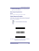
To Add an Output Sequence
1. Scan the Enter Sequence symbol (see Multiple Symbols on page 3-
22
).
2. Code I.D.
On the
Symbology Chart on page A-1, find the symbology to which
you want to apply the output sequence format. Locate the Hex
value for that symbology and scan the 2 digit hex value from the
Programming Chart on page B-5.
3. Length
Specify what length (up to 9999 characters) of data output will be
acceptable for this symbology. Scan the four digit data length from
the Programming Chart. (Note: 50 characters is entered as 0050.
9999 is a universal number, indicating all lengths.) When calculat-
ing the length, you must count any programmed prefixes, suffixes,
or formatted characters as part of the length (unless using 9999).
4. Character Match Sequences
From the
ASCII Conversion Chart (Code Page 1252) on page A-4,
find the Hex value that represents the character(s) you want to
match. Use the Programming Chart to read the alphanumeric
combination that represents the ASCII characters. (99 is the Uni-
versal number, indicating all characters.)
NOTE
To make Output Sequence Editor selections,
you’ll need to know the code I.D., code length,
and character match(es) your application
requires. Use the Alphanumeric symbols from
the
Programming Chart on page B-5 to read
these options.