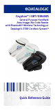
Gryphon™ I GBT/GM4500 General Purpose Handheld Area Imager Bar Code Reader with Bluetooth® Wireless Technology or Datalogic’s STAR Cordless System™ Quick Reference Guide
Datalogic S.r.l. Via S. Vitalino, 13 40012 Lippo di Calderara di Reno Bologna - Italy Telephone: (+39) 051-3147011 Fax: (+39) 051-3147205 ©2011-2018 Datalogic S.p.A. and/or its affiliates An Unpublished Work - All rights reserved. No part of the contents of this documentation or the procedures described therein may be reproduced or transmitted in any form or by any means without prior written permission of Datalogic S.r.l. or its subsidiaries or affiliates ("Datalogic" or “Datalogic S.r.l.”).
Table of Contents END USER SOFTWARE LICENSE AGREEMENT ...................iii About the Scanner ................................................................. 1 Omni-Directional Operating ........................................ 1 Decoding ........................................................................ 2 Setting Up the Reader ........................................................... 2 Positioning the Base Station ....................................... 3 Reader, Cradle and LEDs Description ....
Pick Mode .....................................................................37 Multiple Label Reading ...............................................37 Technical Features ...............................................................38 LED and Beeper Indications ................................................43 Troubleshooting ...................................................................44 Ergonomic Recommendations ...........................................45 Cleaning Procedure .................
END USER SOFTWARE LICENSE AGREEMENT END USER SOFTWARE LICENSE AGREEMENT (EULA) FOR THE GRYPHON™ I GBT/GM4500 PRODUCT SERIES NOTICE TO END USER: BY DOWNLOADING OR INSTALLING THE SOFTWARE, OR BY USING THE DATALOGIC PRODUCT THAT INCLUDES THIS SOFTWARE, THE END USER CONSENTS TO BE BOUND BY THIS AGREEMENT.
END USER SOFTWARE LICENSE AGREEMENT injunctive relief and repossession of all Datalogic Products). 1.6 Without prejudice of the foregoing, End User grants to Datalogic and its independent accountants or consultants the right to examine End User's books, records and accounts during End User's normal business hours to verify compliance with this Agreement.
END USER SOFTWARE LICENSE AGREEMENT BY ANY OTHER PARTY. IN NO EVENT SHALL DATALOGIC'S LIABILITY FOR DAMAGES, IF ANY, WHETHER BASED UPON CONTRACT, TORT (INCLUDING NEGLIGENCE), PRODUCT LIABILITY, STRICT LIABILITY, WARRANTY, OR ANY OTHER BASIS, EXCEED THE PRICE OR FEE PAID BY END USER FOR THE DATALOGIC PRODUCT.
END USER SOFTWARE LICENSE AGREEMENT 9. Third Party Software The Datalogic Product may contain one or more items of third party software which use is governed by separate third party license, unless otherwise stated. 10. Open Source Software Portions of the Software include or operate with Open Source software (“Open Source Software”).
END USER SOFTWARE LICENSE AGREEMENT and construed in accordance with the laws of the State of Oregon U.S.A, without regard to the rules governing conflicts of law.
END USER SOFTWARE LICENSE AGREEMENT Software Product Policy Datalogic reserves the right to ship its products with the latest version of software/firmware available. This provides our customers with the very latest in Datalogic software technology. The only exception to this policy is when the buyer has a signed contract with Datalogic that clearly defines the terms and conditions for making software/firmware changes in products shipped to the buyer.
Gryphon™ I GBT/GM4500 About the Scanner The Gryphon™ product series from Datalogic has been perceived as one of the most innovative readers since the beginning and the new generation of 4500 series wireless readers reinforce this concept thanks to the battery wireless charging system that, coupled with an outstanding design, unchallenged ergonomics and a rich feature set, bring the Datalogic Gryphon GM/GBT4500 series to the TOP of hand held scanners for general purpose applications.
Setting Up the Reader Decoding The Gryphon™ I GBT/GM4500 reliably decodes all standard 1D (linear) and 2D bar codes, including GS1 DataBar™ linear codes, Postal Codes (China Post), Stacked Codes (such as GS1 DataBar Expanded Stacked, GS1 DataBar Stacked, GS1 DataBar, Stacked Omnidirectional). The data stream acquired from decoding a symbol - is rapidly sent to the host. The reader is immediately available to read another symbol.
Setting Up the Reader Positioning the Base Station The base station/charger may be set up in desk application to hold the reader in three different positions, either a horizontal or standing or vertical position, in order to provide the most comfortable use depending on the needs.
Setting Up the Reader Figure 3. Vertical Position This position is preferred when lack of room on the desktop recommends the scanner to be left vertical during recharging. 1. Insert the appropriate parts for the desired base station position. 2. 4 Release the screw situated on the bottom of the cradle's base (the screw will be kept in position by the blue ring).
Setting Up the Reader 3. Using your thumbs, push open the plastic tabs on the bottom of the base to free the wing holders. 4. The stand can now be repositioned in either horizontal or standing position. To improve the robustness (against accidental falls) of the cradle in Presentation Position, it is suggested to add the Shock Absorber addendum as illustrated below.
Reader, Cradle and LEDs Description Reader, Cradle and LEDs Description LEDs on the gun provide information about the battery charging status as well as data transmission.
Connecting the Base Station Connecting the Base Station Figure 5 shows how to connect the Base Station to a terminal, PC or other host device. Turn off the host before connection and consult the manual for that equipment (if necessary) before proceeding. Connect the interface cable before applying power to the Base Station. The Gryphon GBT/GM4500 can also be Powered by the Terminal. When powered by the Terminal, the battery charger is automatically set as Slow charge.
Connecting the Base Station Securing the DC Power Cord (Optional) The DC power cord for the adapter can be secured to the bottom of the base in order to maximize the mechanical retention of the cable itself. The routing of the power cord can be changed to accommodate base station positioning: horizontal, stand or wall mount. The cables can be looped around to the front of the Base Station, or fed directly out the back of the Base Station, as shown in Figure 6. Figure 6.
Connecting the Base Station Host Connection — Verify before connection that the reader’s cable type is compatible with your host equipment. Most connections plug directly into the host device as shown in Figure 7. Keyboard Wedge interface cables have a ‘Y’ connection where its female end mates with the male end of the cable from the keyboard and the remaining end at the keyboard port on the terminal/ PC. Figure 7.
System and Network Layouts System and Network Layouts Stand Alone Layouts Figure 9- Single Reader Layout HOST GRYPHON™ I CRADLE Figure 10- Multiple Reader Layout GRYPHON™ I HOST CRADLE In stand alone systems, each cradle is connected to a single Host.
System and Network Layouts Figure 11- Multiple Stand Alone Layouts Many stand alone connections can operate in the same physical area without interference, provided all readers and cradles in the system have different addresses.
Using the GBT/GM4500 Scanner Using the GBT/GM4500 Scanner Scanner LEDs Specific LEDs on the Gryphon Scanner provide information about: good reading result (3GL), battery status and charging status (with micro USB only). The Battery Status information can be easily retrieved by double-tapping with your fingers on top of the head of the scanner. The following table explains the main colors' combinations provided by the Battery Status LED.
Using the WLC4090 Radio Base Using the WLC4090 Radio Base Radio Base LEDs LEDs on the Gryphon Base provide information about the Base as well as battery charging status, as shown in Figure 12. Figure 12- Gryphon Base LEDs 1 2 2 Table 2. Radio Base LEDs LED 1 2 STATUS Green On = Base is powered Power on / Green Blinking = Base receives data and Data commands from the Host or the Reader.
Replacing the Battery Pack Replacing the Battery Pack Before proceeding, read “Battery Safety” on the preceding pages. Datalogic recommends annual replacement of rechargeable battery packs to ensure maximum performance. Use the following procedure to change the reader’s battery: 1. With a narrow metallic object (i.e. a coin) or a screwdriver, unscrew the battery cover screw.
Replacing the Battery Pack 2. Extract the battery pack from its slot. 3. Insert the new battery in the same position. 4. Replace the battery holder cap, plug in the connector and return the contacts circuit to its previous location. When inserting the new battery into the handle, take care to position the battery and the connector as described above. 5. Insert the cover in the handle and screw it into place.
Using the Gryphon™ I GBT/GM4500 Using the Gryphon™ I GBT/GM4500 The Gryphon™ I GBT/GM4500 normally functions by capturing and decoding codes. The reader is equipped with an internal Motionix™ motion-sensing function which activates the aiming system on device motion.
Using the Gryphon™ I GBT/GM4500 Linear Bar A red beam illuminates the label. The field of view indicated by the aiming system will be smaller when the reader is closer to the bar code and larger when it is farther from the code. Symbologies with smaller bars or elements (mil size) should be read closer to the unit. Symbologies with larger bars or elements (mil size) should be read farther from the unit.
Linking the Reader Linking the Reader Link Datalogic Devices to Base Before configuring the interface it is necessary to link the handheld with the base. To link the handheld and the base simply put it into the base. If the reader was previously linked to another base, you must first scan the Unlink bar code before re-linking to the new base.
Link Scanner as HID device to a Bluetooth host Link Scanner as HID device to a Bluetooth host Use this procedure to send data to a Bluetooth host using the Bluetooth HID profile. 1. If using a Bluetooth adapter on the host device, install any driver provided with the adapter. 2. Scan the Link to Host in HID mode label below to make the scanner visible to the host device. 3. Use the Bluetooth manager of the host device to "Discover new devices" and select "GBT4500 …".
Selecting the Interface Type Selecting the Interface Type Upon completing the physical connection between the reader and its host, proceed directly to Interface Selection below for information and programming for the interface type supported by the reader and scan the appropriate bar code to select your system’s correct interface type, according to your application. For interfaces other than those listed in this manual, see the Gryphon™ I GBT/GM4500 Product Reference Guide (PRG), available online at www.
Selecting the Interface Type RS-232 RS-232 standard interface Select RS232-STD RS-232 Wincor-Nixdorf Select RS232-WN RS-232 for use with OPOS/UPOS/JavaPOS Select RS-232 OPOS USB Com to simulate RS-232 standard interface Select USB-COM-STD* * Download the correct USB Com driver from www.datalogic.
Selecting the Interface Type USB-OEM USB-OEM (can be used for OPOS/UPOS/JavaPOS) Select USB-OEM USB-COMPOSITE USB-Composite Select USB-Composite (Keyboard + COM) IBM46xx IBM46xx Port 9b Select IBM46xx Port 9b 22 Gryphon™ I GBT/GM4500
Selecting the Interface Type ADDITIONAL INTERFACES USB HID POS Select USB HID POS USB Toshiba TEC Select USB Toshiba TEC Quick Reference Guide 23
Selecting the Interface Type Keyboard Interface Use the programming bar codes to select options for USB Keyboard and Wedge Interfaces.
Selecting the Interface Type KEYBOARD (continued) Keyboard Wedge for IBM AT PS2 with alternate key encoding but without external keyboard Select KBD-AT-ALT-NK USB Keyboard with standard key encoding Select USB Keyboard USB Keyboard with alternate key encoding Select USB Alternate Keyboard default value Quick Reference Guide 25
Selecting the Interface Type Scancode Tables Refer to Gryphon I GBT/GM4500 PRG for information about control character emulation for keyboard interfaces. Country Mode This feature specifies the country/language supported by the keyboard.
Selecting the Interface Type COUNTRY MODE (continued) Country Mode = Belgium Country Mode = Croatia* Country Mode = Czech Republic* Country Mode = Denmark* Country Mode = France * Supports only the interfaces listed in the Country Mode feature description.
Selecting the Interface Type COUNTRY MODE (continued) Country Mode = French Canadian* Country Mode = Germany Country Mode = Hungary* Country Mode = Italy Country Mode = Japanese 106-key* * 28 Supports only the interfaces listed in the Country Mode feature description.
Selecting the Interface Type COUNTRY MODE (continued) Country Mode = Lithuanian* Country Mode = Norway* Country Mode = Poland* Country Mode = Portugal* * Supports only the interfaces listed in the Country Mode feature description.
Selecting the Interface Type COUNTRY MODE (continued) Country Mode = Romania* Country Mode = Spain Country Mode = Sweden Country Mode = Slovakia* Country Mode = Switzerland* * 30 Supports only the interfaces listed in the Country Mode feature description.
Programming Programming The reader is factory-configured with a set of standard default features. After scanning the interface bar code from the Interfaces section, select other options and customize your reader through use of the programming bar codes available in the Gryphon™ I GBT/GM45 PRG. Check the corresponding features section for your interface, and also the Data Editing and Symbologies chapters of the PRG.
Programming Numlock This option specifies the setting of the Numbers Lock (Numlock) key while in keyboard wedge interface. This only applies to alternate key encoding interfaces. It does not apply to USB keyboard.
Programming Caps Lock State This option specifies the format in which the reader sends character data. This applies to keyboard wedge interfaces. This does not apply when an alternate key encoding keyboard is selected.
Reading Parameters Reading Parameters Move the reader toward the target and center the aiming pattern and illumination system to capture and decode the image. See "Using the Gryphon™ I GBT/GM4500" on page 16 for more information. The aiming system will briefly switch off after the acquisition time, and if no code is decoded will switch on again before the next acquisition. The illuminator will remain on until the symbol is decoded.
Operating Modes Operating Modes Scan Mode The imager can be set to operate in one of several scanning modes. See the PRG for more information and settings for any of the options: Trigger Single (Default)This mode is associated with typical handheld reader operation. When the trigger is pulled, illumination is turned on and the scanner attempts to read a label.
Operating Modes SCAN MODE ENTER/EXIT PROGRAMMING MODE Scan Mode = Trigger Single Scan Mode = Trigger Hold Multiple Scan Mode = Always On Scan Mode = Trigger Pulse Multiple Scan Mode = Flashing Scan Mode = Stand Mode = default value 36 Gryphon™ I GBT/GM4500
Operating Modes Pick Mode Specifies the ability of the reader to decode labels only when they are close to the center of the aiming pattern, which is the area indicated by the red cross. Pick Mode is a Decoding and Transmission process where bar codes that are not within the configurable distance from the center of the aiming pattern are not acknowledged or transmitted to the host. It is active only while the scanner is in Trigger Single mode.
Technical Features Technical Features Gryphon™ I GBT-GM4500 Electrical Features Power Supply 5V to 14V +/-5% in the Communication Port 5V to 14V +/-5% in the Aux Power Port NOTE: Aux Power Port is recommended when long cables are connected to Communication Port Consumption (Typical) Gun Only: 330 mA @ 3,7V(Operative) Cradle Only: 80 mA @ 5V (Operative) Cradle with Gun in Charge (Scan while Charging): 475 mA (PC host USB) 1150 mA (5V on Aux Power Port) 520 mA (12V on Aux Power Port) Gun Charging via mic
Technical Features Optical Features Optical Format 1/4" Active Imager Size 3896 um (H) x 2453 um (V) Active Pixels 1280 H x 800 V LED source Warm White Emission (wavelength = 350 770 nm) Illumination System Hyper Red Emission (wavelength = 660 nm, DGM model only) IEC 62471 Exempt Risk Group Aiming System RED laser source IEC 60825-1 Class 2 Radiation 1 mW Avg.
Technical Features DOF - Depth of Field (Typical)a Symbology SR HD Code 39 5 mil: 7.0 - 38.0 cm (2.7" 14.9") 10 mil: 2.2 - 58.0 cm (0.8" 22.8") 20 mil: FOV lim. - 110 cm (up to 43.3") 3 mil: 5.0 - 15.0 cm (2.0" - 5.9") 5 mil: 0.5 - 25.0 cm (0.2" - 9.8") 10 mil: 0.5 - 45.0 cm (0.2" - 17.7") EAN13 7.5 mil: 9.0 - 30.0 cm (3.5" - 11.8") 13 mil: 1.0 - 71.0 cm (0.4" - 27.9") 7.5 mil: 2.0 - 23.5 cm (0.8" - 9.2") 13 mil: 1.0 - 40.0 cm (0.4" - 15.7") PDF417 6.6 mil: 6.5 - 24.0 cm (2.6" - 9.4") 10 mil: 2.
Technical Features Environmental Features Physical Dimensions Gun only (lhp): 68.4 x 165.8 x 110.0mm (2.7" x 6.5" x 4.3") Cradle only (lhp): 94.6 x 128.7 x 212.7mm (3.7" x 5.1" x 8.4") Gun on Cradle Horizontal mount (lhp): 94.6 x 134.0 x 212.7mm (3.7" x 5.3" x 8.4") Gun on Cradle Presentation mount (lhp): 94.6 x 170.7 x 183.6mm (3.7" x 6.7" x 7.
Technical Features Regulatory See Regulatory Addendum Radio Features Wireless Technology Range (in open air) Max number of devices per base station 42 Star™ 910 MHz Star™ 433 MHz 50 m 50 m 16 Bluetooth 100 m 7 Gryphon™ I GBT/GM4500
LED and Beeper Indications LED and Beeper Indications The imager’s beeper sounds and its illumination flashes or changes color to indicate various functions or errors on the reader. A “Green Spot” also lights to indicate a good read. The tables below list these indications. Reference the PRG for a more detailed list. Indication LED Beeper Power-up Upper LED flashes/blinks on power-up, however, this may be too rapid to Imager beeps four times view.
Troubleshooting Troubleshooting Problem Possible Cause No power to the Nothing happens when imager. the scan button is pulled. Interface or power cables are loose. LED comes on, but bar code does not decode. Possible Solutions Check system power. Ensure power supply is connected. Ensure all cable connections are secure. Imager not programmed for correct bar code type. Ensure imager is programmed to read the type of bar code scanned. Refer to the PRG for more information.
Ergonomic Recommendations Ergonomic Recommendations In order to avoid or minimize the potential risk of ergonomic injury follow the recommendations below. Consult with your local Health & Safety Manager to ensure that you are adhering to your CAUTION company’s safety programs to prevent employee injury.
Cleaning Procedure Cleaning Procedure Proper cleaning is needed on the external plastic surfaces, output window and electrical contacts to guarantee reliable scanning and charging of the battery. A regular cleaning routine will remove the dust and dirt that may accumulate on the product over time. The maintenance activity may be repeated more frequently depending on the severity of the environment in which the scanner is used. A periodic deeper cleaning is suggested once per month.
Cleaning Procedure Disinfectants may be harsh on metal. They are recommended for use only on enclosures. DO NOT spray or pour cleaner directly onto the unit. DO NOT use solutions in their concentrated form. DO NOT use aerosols, solvents or abrasives. DO NOT use paper towels or rough cloths to clean windows. Cleaning enclosure and window surfaces 1. Moisten a soft cloth with a recommended cleaning solution. Be sure to apply the solution to your cloth first. Wring excessive liquid from the cloth. 2.
Support Through the Website Support Through the Website Datalogic provides several services as well as technical support through its website. Log on to www.datalogic.
Charging the Batteries Charging the Batteries To charge the battery, simply insert the Gryphon into the base. When the scanner is fully seated in the cradle, it will sound a “chirp” to indicate that the cradle has detected the scanner connection. The LEDs on the base (shown in Table 1) will indicate the status of the battery. The Gryphon GBT/GM4500 may get warm during charging: this is normal and does not mean a malfunction. Before using the Battery, read “Battery Safety” in the following section.
Charging the Batteries • Do not place the battery pack in fire or heat. WARNING • Do not connect the positive terminal and negative terminal of the battery pack to each other with any metal object (such as wire). • Do not carry or store the battery pack together with metal objects. • Do not pierce the battery pack with nails, strike it with a hammer, step on it or otherwise subject it to strong impacts or shocks. • Do not solder directly onto the battery pack.
Charging the Batteries Do not place the battery in or near fire, on stoves or other high temperature locations. Do not place the battery in direct sunlight, or use or store the battery inside cars in hot CAUTION weather. Doing so may cause the battery to generate heat, explode or ignite. Using the battery in this manner may also result in a loss of performance and a shortened life expectancy. Do not place the battery in microwave ovens, high-pressure containers or on induction cookware.
Charging the Batteries CAUTION Storage of batteries for long time at fully charged status or at fully discharged status should be avoided. Only in case of long storage, to avoid deep discharge of the battery it is recommended to partially recharge the battery every three months to keep the charge status at a medium level. CAUTION As a reference, run a fast recharge for 20 minutes every three months on unused products to avoid any performance deterioration of the cell.
Datalogic Limited Factory Warranty Datalogic Limited Factory Warranty Warranty Coverage Datalogic warrants to Customer that Datalogic's products will be free from defects in materials and workmanship for a period of three (3) years from product shipment. Datalogic hardware products are warranted against defects in material and workmanship under normal and proper use.
Datalogic Limited Factory Warranty Warranty Exclusions The Datalogic Factory Warranty shall not apply to: (i) any product which has been damaged, modified, altered, repaired or upgraded by other than Datalogic service personnel or its authorized representatives; (ii) any claimed defect, failure or damage which Datalogic determines was caused by faulty operations, improper use, abuse, misuse, wear and tear, negligence, improper storage or use of parts or accessories not approved or supplied by Datalogic; (i
Datalogic Limited Factory Warranty NOTES Quick Reference Guide 55
Datalogic Limited Factory Warranty NOTES 56 Gryphon™ I GBT/GM4500
www.datalogic.com Datalogic S.r.l. Via S. Vitalino, 13 | Lippo di Calderara di Reno 40012 BO| Italy | Telephone: (+39) 051-3147011 Fax: (+39) 051-3147205 ©2018 Datalogic S.r.l. • All rights reserved. Datalogic and the Datalogic logo are registered trademarks of Datalogic S.p.A. in many countries, including the U.S.A. and the E.U. Motionix and Gryphon are trademarks of Datalogic S.p.A. or of Datalogic Group companies, registered in the U.S. 820096214 Rev.