Operator’s Manual
Copyright Information CG Times (based upon Times New Roman) and CG Triumvirate are trademarks of the AGFA Monotype Corporation. Windows and Windows NT are trademarks of the Microsoft Corporation. NetWare and Novell are registered trademarks of Novell, Inc. Ethernet is a registered trademark of Xerox Corporation. All other brand and product names are trademarks, service marks, registered trademarks, or registered service marks of their respective companies.
Agency Compliance and Approvals: C US Listed UL60950-1 2nd Edition, Information Technology Equipment CSA C22.2 No.
Important Safety Instructions Throughout the literature accompanying this unit, the exclamation point within an equilateral triangle is intended to alert you to the presence of important operating and maintenance instructions. This unit has been carefully designed to provide years of safe, reliable performance.
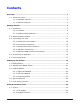
Contents Overview .................................................................................................... 1 1.1 About the Printer ...............................................................................1 1.1.1 Standard Features.....................................................................2 1.1.2 Optional Features......................................................................3 Getting Started ...................................................................................
4.2 The System Menu ............................................................................ 32 4.2.1 Media Settings........................................................................ 33 4.2.2 Print Control........................................................................... 36 4.2.3 Printer Options ....................................................................... 38 4.2.4 System Settings ..................................................................... 46 4.2.5 Communications .....
5.7.1 Soft Reset.............................................................................. 97 5.7.2 Level One Reset...................................................................... 97 5.7.3 Level Two Reset...................................................................... 97 5.8 Updating the Firmware ..................................................................... 98 5.9 Updating the Boot Loader................................................................ 100 5.10 Fonts .................
Appendix F ............................................................................................. 143 Saving a Configuration File..................................................................... 143 Appendix G ............................................................................................. 145 Ribbon Saver Overview ......................................................................... 145 Glossary ....................................................................................
1 Overview 1.1 About the Printer Congratulations on your purchase of an A-Class Mark II printer. This print engine (hereafter referred to as “the printer” and, when necessary, by model) is designed for professional integration into an industrial applicator system. This manual provides all the information necessary for installation, setup and operation of the printer.
1.1.1 Standard Features This printer offers the following standard features: • Right-handed or left-handed configurations • Electronics card cage • 8 MB Flash downloadable program memory • 16 MB DRAM memory • User accessible memory for graphics, fonts, and label format storage • Two RS-232 serial interfaces (one of which is also RS-422/RS-485 capable) • One IEEE 1284 compliant parallel interface • One Ethernet 10/00 interface • One USB v1.
1.1.2 Optional Features The following optional features are available: • DMXrfNetII A wireless Network Interface Controller with multiple operating system and protocol support, including trap functions.
Installing Printer Options The table below lists competency level recommendations for the installation of the various options. For detailed information regarding an option, contact a dealer or Datamax-O’Neil Technical Support.
2 Getting Started 2.1 Unpacking The printer is carefully packaged for transit. Upon arrival, inspect the shipping carton(s) for damage; if evident, immediately report the damage to the freight company. In order to operate the printer, remove all packaging material: 1. With the Shipping Carton arrows pointing upward, open the Shipping Carton and remove the Accessories Box and the Top Foams. 2. Carefully lift the wrapped Printer from the carton and place it on a solid level surface.
2.1.1 Contents Check the contents of the carton for the following items: • Printer • Power cord • Accessories CD-ROM • Any additionally purchased items or options. 2.1.2 Additional Requirements Other items can also be needed for operation: • Media (and ribbon, if necessary); see Section 7.2. • Interface cables; see Section 2.3 (Host Connections) and Appendix D (Applicator). • Software; see the Accessories CD-ROM for Windows Drivers and basic labeling software.
2.2 Mounting Requirements Before installing the printer, ensure that the environmental conditions of the site fall within the range specified in Section 7, and always avoid the following environments: • • Do not place the printer in direct sunlight or near a heat source; and, Do not place the printer where it will be exposed to liquids, or excessive dust or dirt. Consider the dimensions of the printer before attaching it to the applicator station.
A-4xxx models 9.67” (246mm) 11.81” Front View, Peel Assembly lowered: (300mm) 2.25” (57mm) 7.68” (195mm) Side View: 10.45” (266mm) 15.35” (390mm) 12.51” 7.66” (318mm) (195mm) Side View, Cover raised: 20.
A-6xxx models 9.67” (246mm) 11.81” Front View, Peel Assembly lowered: (300mm) 2.25” (57mm) 9.68” (246mm) Side View: 10.45” (266mm) 17.35” (441mm) 7.66” (195mm) 14.51” (369mm) Side View, Cover raised: 22.
Peel Point Dimension Peel Bar 10 See Appendix C for the PE-Series printer’s dimension.
2.3 Connecting to a Host Ensure that the Power Switch is OFF when making printer connections. The printer can be interfaced to a host via the parallel, serial, Ethernet and USB ports. (Ethernet users, consult the documentation that accompanied the option.) Following power-up (or after a period of inactivity), interface port selection occurs automatically upon detection of valid data. If the incoming data flow stops and the Host Timeout period (see Section 4.2.
2.3.1 Parallel Port Connections The parallel interface requires a Centronics IEEE 1284 cable with a 36 pin male connector. Bidirectional mode is IEEE 1284 compliant, allowing data to be returned to the host. 2.3.2 Serial Port Connections Serial Port A supports RS-232C and RS-422/RS-485 communications; COM C and COM D support RS-232 (see Appendix D for exceptions). Pin-outs are given below.
COM D Port Connections COM D RS-232 Cable Host DB-9S Printer RJ45P +5 VDC +5 VDC 1 1 RXD 2 4 TXD TXD GROUND 3 5 RXD 5 3 GROUND DTR 4 DSR 6 2 RTS CTS 8 9 NC 7 NC NC 7 CTS 8 DTR 6 Part # 32-2603-00 2.3.3 RS-422/485 Communications To use RS-422/485 communications (Port A, only), the main logic card must be reconfigured: Always wear a wrist strap and follow standard ESD prevention measures when handling the Main Logic Card. 1.
3. Slide the Main Board out of the printer then move the jumpers according application: • For RS-422/485 operation, place the jumper across pins E4 and E5; • For +5VDC on Pin 1, place the jumper across pins E1 and E2; or, • For RS-232 operation (default), place the jumper across pins E5 and E6; • For no voltage on Pin 1 (default), place the jumper across pins E2 and E3. Communications Jumpers +5 Volt Jumper 4.
2.3.4 USB Port Connections The Universal Serial Bus port requires a standard USB cable. This USB Port is a device-end only connection. Never attach a keyboard, mouse, modem, etc. to this port; damage can result. 2.3.5 SDIO and USB Host Port Connections If equipped with the Secure Digital Input Output (SDIO) and USB Host Ports, the printer can accept external storage devices for fonts, graphics, label formats, and firmware files.
To copy firmware stored on a module to the printer: 1. Press the TEST button then select User Defined Label. 2. Select the module ID and the firmware file. To print files stored on a module: 1. Press the TEST button and then select User Defined Label. 2. Select the module ID then the file to print. To print directly from stored files at power-up, see User Label mode in Section 4.2.4. To print a previous label format that is stored in memory: 1. Press the MENU button then select Printer Options.
2.5 Connecting Power The power cord connects to the AC receptacle on back of the printer. Make the connection and power-up the printer as follows: 1. Ensure that AC power to the host computer and applicator system are OFF. 2. Ensure that the printer’s Power Switch is OFF. Power Switch 3. Connect the AC Power Cord to the printer and then to a properly grounded outlet. 4. Turn ON (in the following order) the host computer, the applicator system, and then the printer.
18 A-Class Mark II
3 Setting up the Printer 3.1 Loading Media Load media according to its type and desired output: 1. Open the Access Cover and raise the Head Lift Lever. If your printer is equipped with Rear Pinch Roller option open the Pinch Roller by pulling outward on the Release Knob. Rear Pinch Roller Option Release Knob 2. Route the Media between the Media Posts, through the Media Sensor, over the Peel Bar, and out of the printer, as shown below.
3. To peel die-cut labels after printing, press down on the Peel Assembly Release Lever to lower the Peel Assembly; otherwise, proceed directly to Step 6. Peel Assembly Release Lever Media Peel Assembly 4. Remove the labels from 12 inches (30 cm) of the Media Liner. Route the Media Liner down to the Peel Assembly, over the Latch Roller, and through the Slot as shown below.
5. Pull the Media Liner through the Slot in the Peel Assembly until all slack is removed. Lifting from the center, raise the Peel Assembly until it locks into place.
6. Position the Media Guide lightly against the side of the media. Media Guide Head Lift Lever Locking Post 7. Adjust the Media Sensor over the labels (see Section 3.2). 8. If printing on thermal transfer media, load ribbon (see Section 3.3); otherwise go to Step 9. 9. Lower the Head Lift Lever until it is completely and securely engaged onto the Locking Post. 10.
3.2 Adjusting the Media Sensor Position the Media Sensor to detect labels as follows: 1. Ensure that media is routed through the Media Sensor; see Section 3.1. Media Media Sensor Media Eye Mark Media Sensor Adjustment Knob 2. Depending on the type of media being used, rotate the Media Sensor Adjustment Knob until the Eye Mark on the Media Sensor is positioned according to the table below.
3.3 Loading Ribbon Load ribbon (for thermal transfer media) according to its coated side and the printer model. Using a ribbon slightly wider than the media (and liner) is recommended for added protection against abrasive wear. 3.3.1 Right Hand Models Load ribbon as follows: 1.
2. With the Head Lift Lever raised, route the Ribbon under the Lower Idler, over the Ribbon Shield and Upper Idler, and then clockwise around to the Ribbon Take-Up Hub. 3. Rotate the Ribbon Take-Up Hub clockwise several times to secure the Ribbon. 4. Lower and lock the Head Lift Lever then close the access cover.
3.3.2 Left Hand Models Load ribbon as follows: 1. Orient the unwind position of the Ribbon according to the coated side (CSI or CSO) and then slide the Ribbon Roll completely onto the Ribbon Supply Hub, as shown below: Ribbon Supply Hub Ribbon Supply Hub CSO Ribbon Roll CSI Ribbon Roll Ribbon Ribbon CSO Ribbon CSI Ribbon 2. With the Head Lift Lever raised, route the Ribbon under the Lower Idler, over the Ribbon Shield and Upper Idler, and then counterclockwise around to the Ribbon Take-Up Hub. 3.
Ribbon Take-Up Hub Ribbon Take-Up Hub Head Lift Lever Head Lift Lever Upper Idler Upper Idler CSO Ribbon Roll Ribbon Shield CSI Ribbon Roll Ribbon Shield Ribbon Ribbon Lower Idler CSO Ribbon Lower Idler CSI Ribbon 3.3.3 Removing Ribbon After the ribbon supply has been exhausted, grasp the used ribbon and, while squeezing, pull to collapse the Ribbon Take-Up Hub then slip off the ribbon. Next, slip off the empty core from the Ribbon Supply Hub.
3.4 Quick Calibration Perform Quick Calibration during initial printer setup or after changing the media, but not if using continuous media. • Media with long gaps between labels may require a PAPER OUT DISTANCE change; see Section 4.2.1. Also, if UNCALIBRATED is displayed, see Section 5.2.1. With media loaded and the Media Sensor adjusted, press and hold the FEED Key until at least two complete labels advance before releasing the key.
4 Using the Control Panel 4.1 Layout The Control Panel is an event-driven user interface composed of a graphics display and Soft Keys. Time and Date Printer Status Line Main Display Area Current State Icons Fault/Error Stop/Paused Receiving Data Soft Key Labels Soft Keys 4.1.
Icon Description Initialization, typically brief (but a damaged or invalid printhead can delay the process). M PL Z Display large fonts; see Section 4.1.2. ENU DPL Input Mode – DPL; see Section 4.2.4. LINE Input Mode – LINE; see Section 4.2.4. PL I RFID PL B Input Mode – Emulation; see Section 4.2.4. RFID detected. SD SD memory card detected. USB HOST USB memory (or keyboard) detected. Wired network detected. Server inaccessible. WLAN associated with Access Point.
4.1.2 Keypad Functions The Soft Keys (see Section 4.1) control printer functions: • The Soft Keys are mode-dependent, changing functions as needed. Depending upon the printer’s state, many functions can be accessed by pressing (or pressing and holding for various durations) the keys and buttons: Keypad Functions Printer State Pressing Sequence Related Section Calibration, Empty Value Idle Long PAUSE & FEED 5.2 Calibration, RFID Option Idle Long FEED & TEST 4.2.
4.2 The System Menu The System Menu is composed of seven menu branches: MEDIA SETTINGS PRINT CONTROL PRINTER OPTIONS SYSTEM SETTINGS COMMUNICATIONS DIAGNOSTICS MCL OPTIONS To enter the System Menu, press the Menu Soft Key. (This places the printer in Menu mode, taking it offline, halting the processing of new data.) 32 Prompts may appear before menu access is granted or before changes are enacted; see Section 5.1.1. MENU MODE controls the access level; see Section 4.2.4.
4.2.1 Media Settings The Media Settings menu contains label and ribbon settings, and printhead maintenance selections. Menu Item MEDIA TYPE Details Selects the printing method, where: DIRECT THERMAL Sets printing for heat reactive media. THERMAL TRANSFER Sets printing for media that requires ribbon to produce an image. SENSOR TYPE Selects the Top Of Form (TOF) sensing method used to determine the leading edge of the label, where: GAP CONTINUOUS Senses the gaps or notches in the media.
Media Settings (continued) Menu Item RIBBON LOW OPTIONS RIBBON LOW DIAMETER (1.0 0 – 2.00 in.) 1.38 PAUSE ON RIBBON LOW Defines the response when THERMAL TRANSFER is selected and the ribbon supply diminishes, where: Sets the threshold that will trigger a Low Ribbon Warning prompt, where: Is the outer diameter size of the roll. Sets the printer to pause when the Ribbon Low Diameter setting is met, where: ENABLED Forces you to press the PAUSE Key to proceed with the print job.
Media Settings (continued) Menu Item PRINTHEAD CLEANING CLEAN HEAD SCHEDULE 0 – 200 in.(* 1000) 000 Details Controls printhead cleaning alerts and functions, where: Specifies the inch (or centimeter) count (multiplied by one thousand) at which to clean the printhead. If this count is exceeded three times, a Head Cleaning Fault will occur. Zero (000) disables this function. CLEAN HEAD COUNTER Indicates the number of inches (or centimeters) since a cleaning was last initiated.
4.2.2 Print Control The Print Control menu contains print quality, throughput and formatting functions: Menu Item Details HEAT Controls the burn-time of the printhead (selectable as “Heat” in most labeling programs), where: (0 – 30) 10 PRINT SPEED Is the number based on duration, corresponding to print darkness. XX.X in/sec Controls the rate of label movement during printing, where: Is the speed; see Appendix B for the model dependant default and range. FEED SPEED XX.X in/sec REVERSE SPEED X.
Print Control (continued) Menu Item PRESENT DISTANCE (0 – 4.00 in.) AUTO 0.00 Details Sets the label stop position, where: Is the label output distance. The default setting (Auto) configures this distance according to the positioning requirements of the attached device (e.g., tear bar, cutter, etc). TOF PRECEDENCE When set to 0.01 in., NONE is assumed; a zero (0) positioning value will be used.
4.2.3 Printer Options The Printer Options menu contains module, file handling, and option functions: Menu Item MODULES DIRECTORY PRINT FILE PROCESS FILE FORMAT MODULE Details Controls memory handling functions, where: Allows viewing and printing of available space and file types (including plug-ins) present on a module. Only detected modules will be listed, and selecting ALL will display all results; see Appendix A. Prints selections from listings of available files, including .dlb, .dpl, .prn and .
Printer Options (continued) Menu Item CUTTER MODE Details Controls the Cutter option, where: Sets the detection method and response of the printer, where: DISABLED Disables the option. AUTO Detects, enables, and sets the label stop location for the cutter; if not detected, the option will be ignored. ENABLED Enables and sets the label stop location for the cutter; if not detected, a fault will be generated.
Printer Options (continued) Menu Item RFID Details Controls the RFID option, where: If not detected, this selection will result in a DISABLED message. RFID MODULE DISABLED Disables the option. HF Selects the High Frequency (13.56 MHz) option. UHF MULTI-PROTOCOL Selects the Ultra High Frequency (868-956 MHz) option. RFID POSITION (1.10 - 4.00 in.) 1.
Printer Options (continued) Menu Item DSFID VALUE (00 – FF) 00 DSFID LOCK Details Sets the Data Storage Format Identifier value, where: Is the hex value. Locks the Data Storage Format Identifier value, where: ENABLED Is write-protected. DISABLED Is not protected. EAS VALUE (00 – FF) 00 AUDIO INDICATOR Selects the Electronic Article Surveillance value, where: Is the hex value. Controls the buzzer, where: ENABLED Allows sound. DISABLED Inhibits sound.
Printer Options (continued) Menu Item TAG DATA SIZE Sets the tag data size, where: 96-BIT Selects 96 bits (24 hexadecimal characters or 12 ACSII characters). 64-BIT Selects 64 bits (16 hexadecimal characters or 8 ACSII characters). POWER ADJUST (-04 04) 000 KILL CODE 00 00 00 00 ACCESS CODE 00 00 00 00 GEN 2 LOCK ACTION Adjusts the applied power, where: Is the power level, in 1.0 dBm increments. Sets the code to permanently deactivate the tag, where: Is the code, in the form B3, B2, B1, B0.
Printer Options (continued) Menu Item LOCK AFTER WRITE Details Allows the tag to be locked after programming, where: ENABLED Locks the tag. DISABLED Does not lock the tag. RETRY ATTEMPTS (0 - 9) 3 PERFORM CALIBRATION YES NO SET DEFAULTS Sets the number of retry attempts, where: Is the retry count before a fault is declared.
Printer Options (continued) Menu Item GPIO PORT GPIO DEVICE Details Controls the optional Applicator Interface Card’s GPIO function, where: Sets the option to work with a specific device type, where: DISABLED Disables the option. APPLICATOR Enables parameters for related label applicator functions: • Completion upon last SOP, de-asserts Data Ready (DRDY); • FEED allowed at any time; and, • DRDY upon PAUSE.
Printer Options (continued) Menu Item END OF PRINT Details Sets the type of output signal generated to indicate EOP, where: LOW PULSE Outputs a low pulse upon completion. HIGH PULSE Outputs a high pulse upon completion. ACTIVE LOW Outputs a logic low upon completion. ACTIVE HIGH Outputs a logic high upon completion. RIBBON LOW Sets the low ribbon signal (as determined by RIBBON LOW OPTIONS; see Section 4.2.1), where: ACTIVE LOW Outputs a logic low when the roll size reaches the setting.
4.2.4 System Settings The System Settings menu contains operating, control, and formatting functions: Menu Item MENU MODE Details Sets the menu access level, where: USER MENU Accesses limited basic menu items. ADVANCED MENU Accesses all menu items. CONFIGURATION FILE Controls the creation, storage, and recall of printer configuration files (see Appendix E), where: RESTORE AS CURRENT Lists the files available and then, after selection, reconfigures the printer according to that file.
System Settings (continued) Menu Item DOUBLE BYTE SYMBOLS Details Selects the code page (see the Class Series 2 Programmer’s Manual) used for the ILPC option (unless otherwise specified), where: JIS Selects Japanese Industry Standard. SHIFT JIS Selects Shift Japanese Industry Standard. EUC Selects Extended UNIX Code. UNICODE Selects Unicode (including Korean). GB Selects Government Bureau Industry Standard, Chinese (PRC). BIG 5 Selects Taiwan encoded.
System Settings (continued) Menu Item PRINTER KEY Details Identifies the unique key number of the printer, in the form: vvvv-cwxx-yyyyyy-zzz Where: vvvv – Represents the printer model number. cwxx – Represents the hardware and software levels, where: c – Is the printer class. w – Is the main board hardware level. xx – Is the software feature level: 10 = Standard DPL 20 = Internal CG Times Font Increases beyond the feature level require authorization. yyyyyy – Is a manufacturing date code.
System Settings (continued) Menu Item FORMAT ATTRIBUTES Details Defines the way overlapping text, bar codes, and graphics are printed, where: TRANSPARENT Prints intersecting areas, for example: XOR Obliterates intersecting areas, for example: OPAQUE Overwrites intersecting areas with those last formatted, for example: HEAD BIAS Allows the dot zero orientation to flip, as viewed from the label exit, where: Switching this setting will reverse all media movement directions.
System Settings (continued) Menu Item PAUSE MODE Details Allows interactive print control, where: ENABLED Prints only as the PAUSE Key is pressed. DISABLED Prints normally, without user intervention. PEEL MODE Allows the SOP signal to initiate (via the optional GPIO port) the feeding of labels, where: ENABLED Feeds labels only after SOP is received. DISABLED Feeds labels regardless of SOP.
System Settings (continued) Menu Item UNITS OF MEASURE Details Sets the measurement standard of the printer, where: IMPERIAL Uses inches. METRIC Uses millimeters and centimeters. INPUT MODE Defines the type of processing that occurs when data is received, where: See the Class Series 2 Programmer’s Manual for detailed information. DPL Processes data for standard DPL printing. LINE Processes data for Line mode (template) printing.
System Settings (continued) Menu Item COLUMN EMULATION (XXX – XXX DOTS) XXX Details Allows the column dot count to be adjusted, where: Is the printed number of dots per inch (or mm) thereby reducing the width of the produced format; see Appendix B. ROW EMULATION No adjustment occurs at the default setting.
System Settings (continued) Menu Item FONT EMULATION STANDARD FONTS CGTIMES USER ID S50 LABEL STORE Details Allows font substitution, where: Prints using standard (internal) fonts. Prints using CG Times font. Prints using a downloaded font. Determines the data content when retrieving stored label formats, where: STATE & FIELDS Recalls the printer state (i.e., heat, speeds, etc.) and the formatting commands for a stored label. FIELDS ONLY Recalls the formatting commands for a stored label.
System Settings (continued) Menu Item FAULT HANDLING LEVEL Details Determines the label disposition and user action if a fault occurs, where: Sets the printer response upon declaration of a fault, where: NO REPRINT Stops printing and declares a fault. Then, following correction of the problem, the FEED Key must be pressed to clear the fault. STANDARD Stops printing and declares a fault.
System Settings (continued) Menu Item VOID DISTANCE (0.10 to 2.00 in.) 0.50 Details Sets the distance to print VOID on a faulted label, where: Is the distance, measured from the trailing edge, which establishes the text size. RETRY COUNT (0 – 3) 1 VOID will not be printed if insufficient text space exists or if the fault occurred after printing completed. Also, the text can be customized; see the Class Series 2 Programmer’s Manual.
4.2.5 Communications The Communications menu contains interface port and host control functions: Menu Item SERIAL PORT A BAUD RATE 1200 BPS 2400 BPS 4800 BPS 9600 BPS 19200 BPS 28800 BPS 38400 BPS 57600 BPS 115000 BPS PROTOCOL Controls the RS-232 communications settings for Serial Port A, where: Sets the serial communication rate, where: Is the serial speed in Bits Per Second. BOTH Sets the data flow control method (handshaking), where: Uses XON/XOFF and CTS/DTR. SOFTWARE Uses XON/XOFF.
Communications (continued) Menu Item SERIAL PORT C Details Controls the settings for the Applicator Interface COM C (J4) port, where the setting selections are the same as those given for the SERIAL PORT A. SERIAL PORT D Controls the settings for the Applicator Interface COM D (J3) port, where the setting selections are the same as those given for the SERIAL PORT A. PARALLEL PORT A PORT DIRECTION The maximum baud is 38.4K BPS. The maximum baud is 38.4K BPS.
Communications (continued) Menu Item WLAN ADHOC Details Selects the DMXrfNetII default parameters, where: NO Exits the menu item without changing the current settings. YES Restores WiFi defaults and initiates infrastructure mode with an SSID of “Any.” All existing access point associations will be deleted then established with the closest available. (Useful when moving the printer to a geographically distant location.
Communications (continued) Menu Item SUBNET MASK 255.255.255.000 GATEWAY 192.168.010.026 SNMPTRAP DESTINATION 000.000.000.000 Details Specifies the static Subnet Mask Address, where: Is the address in standard octet format. Specifies the network Gateway Address, where: Is the address in standard octet format. Specifies the SNMP Trap Address, where: Is the address in standard octet format where SNMP traps will be sent when SNMP service is installed on your receiver.
Communications (continued) Menu Item FTP Sets File Transfer Protocol to transfer data, where: ENABLED Allows FTP. DISABLED Disables FTP. MTU (512 - 65515) 01500 GRATUITOUS ARP (0 - 2048) 0000 Sets the Maximum Transmission Unit packet size, where: Is the packet size, in bytes. Sets the Address Resolution Protocol notification rate, where: Is the time, in minutes. PORT NUMBER Sets the network communications port, where: (1 - 65535) 09100 TCP KEEPALIVE Is the Port Number.
Communications (continued) Menu Item NETWORK REPORT Details Allows viewing or printing of the network status report, where: VIEW Displays the report. PRINT Prints the report: NETWORK REPORT WED 03:15PM 23JUL2008 CURRENT PRINTER INFO MACO: 00:0D:70:0B:8B:B9 IP ADDRESS: 192.168.10.26 SUBNET MASK: 255.255.255.0 GATEWAY: 192.168.10.26 DHCP: ENABLED SNMP: ENABLED PORT NUMBER: 9100 NETBIOS NAME: DMX_038BB9 WLAN MODULE MODULE FW VERSION: 4.3.0.24 RADIO FW VERSION: 1.1.1.111.8.4.0.
Communications (continued) Menu Item FEEDBACK CHARACTERS Details Allows the return of printer codes, where: ENABLED Sends the host a Hex 1E (RS) after each label and a Hex 1F (US) after each batch successfully prints. DISABLED Sends no feedback characters. ESC SEQUENCES Sets handling for data containing invalid ESC sequences, where: ENABLED Processes commands normally. DISABLED Ignores ESC control codes during processing (as some systems send “banners” to the printer).
Communications (continued) Menu Item CNTRL-CODES (DATA) Details Determines how host Control Codes are handled, where: ENABLED Processes software commands normally. DISABLED Controls the setting via the menu; see CONTROL CODES, above. STX-V SW SETTINGS Determines how a host option enable command is handled, where: ENABLED Processes the command normally. DISABLED Controls settings via the menu; see Section 4.2.3.
Communications (continued) Menu Item PROCESS SOH (DATA) Details Determines the response to an Immediate Command (e.g., Get Status, Module Storage, etc.), where: DISABLED Processes commands normally. ENABLED Interrupts operations upon SOH receipt to process the command. 4.2.6 Diagnostics The Diagnostics menu contains testing functions: Menu Item HEX DUMP MODE Determines how the printer handles host data, where: DISABLED Processes data normally.
Diagnostics (continued) Menu Item Details TEST GPIO Tests the Applicator Interface CCA’s GPIO function, where: MONITOR GPIO INPUT SOP 1 FEED 1 i1 1 i2 1 i3 1 PAUSE 1 i4 1 REPRT 1 i5 1 i6 1 TEST GPIO OUTPUT EP RL SR MO RO DR OF 1 1 1 1 1 1 1 o1 1 o2 1 o3 1 o4 1 o5 1 PRINT SIGNAL INFO TEST RFID o6 1 Displays input signal logic values for Start of Print (SOP), Feed, Pause, Reprint (REPRT), and six unassigned input lines. (The values given here are examples only.
Diagnostics (continued) Menu Item Details PRINT TEST RATE (min) Allows a label-to-label delay when batch printing Test Labels, where: Is the selected interval, in minutes.
Diagnostics (continued) Menu Item ICON DESCRIPTIONS Details Identifies the printer icons (see Section 4.1.1), where: SYSTEM ICONS Displays system indicators. NETWORK ICONS Displays network indicators. INPUT TYPE ICONS Displays input mode indicators. OPTIONS ICONS Displays detected option indicators. 4.2.
4.3 The Test Menu The (Quick) Test Menu contains resident format selections that are printed at selected heat and speed settings. Use full width media to capture the entire format; otherwise, adjust the printer and set the Label Width. To enter the Test Menu, press the TEST Soft Key, then the Enter Soft Key to view the available test label formats (In Test mode the printer is offline, halting the processing of new data.) • To print a format, scroll to that item then input a quantity and press ENTER.
4.3.3 Test Label The Test Label serves as an indicator of printhead functionality. The format consists of patterns that exercise all thermal elements. 4.3.4 Validation Label The Validation Label serves as an overall quality indicator. Consisting of compliant fence and ladder bar codes, assorted font sizes, and black fill patterns, this format can be used to ensure conformance as well as aesthetics. 4.3.
4.3.6 Print Last Label Print Last Label reprints the most recent format output by the printer. If a job was cancelled prior to completion, or if power was removed since the last print job and this label request, VOID will be printed. 4.3.7 User-Defined Label The User-Defined Label allows a template to be populated by variable data (via the printer’s control panel or a USB QWERTY keyboard). The template is a stored label format, where fields delimited by an ampersand (&) become variable.
5 Operating, Adjusting and Maintaining the Printer 5.1 Displayed Messages During operation (when not in Menu or Test mode) the printer displays several types of information: • Prompts and Condition Messages (see below); and • Fault and Warning Messages (see Section 6.1.2). 5.1.1 Prompts and Condition Messages Prompts appear when an action is required during operation, while Condition Messages indicate an operational state.
Prompts and Condition Messages (continued) Displayed Message CANCEL REPRINT ENTER KEY = YES CLEARING FAULTS Description The CANCEL or TEST Key was pressed during a fault. (See FAULT HANDLING / VOID AND RETRY, Section 4.2.4.) Action Press ENTER to cancel the reprint. The FEED Key was pressed following a fault and now the No action is required. printer is attempting to clear the condition. The network card is initializing, a normal condition following power-up or a reset. No action is required.
Prompts and Condition Messages (continued) Displayed Message Description REMOVE RIBBON The TEST Key was pressed and held, or CLEAN HEAD NOW was selected, but ribbon is installed. PRESS ANY KEY SAVE CHANGES? SUCCESSFUL Database changes were made that require confirmation. Action Remove ribbon and press any key to proceed. Press YES to accept the changes, or NO to discard them. If required, a reset will automatically occur. The selected operation was successfully completed.
5.2 Calibration Calibration ensures correct media detection, and should be performed when Quick Calibration fails (see Section 3.4). 5.2.1 Standard Method Three calibration samples are required: • Empty – with nothing over the sensor; • Gap (or Mark) – with media liner, a notch, or a mark over the sensor; and, • Paper – with the label (and liner, if any) over the sensor. Calibrate the printer as follows: Ensure that the correct SENSOR TYPE is selected; see Section 4.2.1.
Step Action Displayed Message For die-cut media: Proceed according to the media type: • Die-Cut –Remove a label E or two from the liner then install the media. Position the Media Sensor under the liner area and press the ESC Key. SCAN BACKING PRESS ESC KEY - Or, for reflective media: SCAN MARK PRESS ESC KEY • Notched (or Reflective) – Install media. Position the Media Sensor under a notch (or black mark) and press the ESC Key. • Continuous – Press the ESC Key.
Step Action Displayed Message Comment Calibration was successful. G Observe the calibration result. CALIBRATION COMPLETE CALIBRATION COMPLETE H Press the ESC Key repeatedly to exit menu mode. Followed by... READY If ‘Warning Low Backing’ is displayed, calibration was successful (for possible messages see Section 5.1). When calibrating gap or reflective media, press and hold the FEED Key until at least one label is output. The printer is now ready for use. 5.2.
Step Action Displayed Message Comment B Press the MENU Key. Then, with MEDIA SETTINGS highlighted, press the ENTER Key. MEDIA SETTINGS Press the ESC Key to abort this procedure. C Using the DOWN Key, scroll to SENSOR CALIBRATION then press the ENTER Key. Scroll to ADVANCED ENTRY and press the ENTER Key. ADVANCED ENTRY Press the ESC Key to abort this procedure. D Scroll to SENSOR GAIN then press the ENTER Key. SENSOR GAIN Press the ESC Key to abort this procedure.
Step G Action Press the UP Key, incrementing the Gain Number by one, and then press the ENTER Key. Record the sensor reading as a Label Value in the table. Repeat this step for each of the remaining Gain Numbers. Gain Number 00 01 02 … 31 Step Action Displayed Message Comment GAIN TRAN *01 (0 – 31) - Or, for reflective media: GAIN REFL *01 (0 – 31) Sample Calibration Table Label Value TOF Value 252 250 248 … 009 Displayed Message Where ‘yyy’ represents the current sensor reading.
Step Action Lower and latch the Head Lift Lever. I Using the UP or the DOWN Key, set the Gain Number to 00 and then press ENTER. Record this reading as a TOF Value for Gain Number 00 in the table. Gain Number 00 01 02 … 31 Step J Action Use the keys to increment the Gain Number by one and then press the ENTER Key. Record the TOF Value. Repeat this step for each Gain Number.
Step K Action In the table, where both the Label Value and TOF Value are at least 20, subtract the amounts and record the result as a Difference Value (see below). Identify the largest Difference Value and then the corresponding Gain Number. Gain Number 00 01 02 … 15 16 17 18 19 … 31 Step L Action Scroll to the Gain Number determined in the previous step and then press the ENTER Key.
Step Action Displayed Message Comment GAIN TRAN *18 (0 – 31) Where ‘yyy’ represents the current sensor reading. Complete a table (see example below) using three new measurements, as follows: (A) Raise the printhead assembly. Place the label (attached to liner) in the Media Sensor then lower and latch the Head Lift Lever. Record the sensor reading as P. M (B) Raise the printhead assembly. Place the liner, notch, or mark in the Media Sensor then lower and latch the Head Lift Lever.
Step Action Displayed Message Comment PAPER SENSOR LEVEL P* 198 G*000 E*000 GAP SENSOR LEVEL P* 198 G*084 E*000 O Using the DOWN Key set the ‘Paper’ level to the value determined in the previous step and press the ENTER Key. Repeat this step for the ‘Gap’ (or ‘Mark’) and the ‘Empty’ value. EMPTY SENSOR LEVEL P* 198 G*084 E*014 -Or, for reflective media: The selection will change to indicate the item for entry.
Step Action Displayed Message Comment The printer is ready for use. Q Press and hold the FEED Key until at least one label has been output. READY If the calibration attempt fails, try desensitizing the sensor as follows: Go to MEDIA SETTINGS / SENSOR CALIBRATION / ADVANCED ENTRY / SENSOR GAIN and lower the corresponding GAIN SETTING by one. Exit the menu, saving the changes. Test the media at the new setting and if necessary repeat until a usable GAIN SETTING is obtained. 5.
Head Lift Lever Leveling Cam 2. While observing the printed output, rotate the Leveling Cam counterclockwise until the image fades across the label, as shown in Example 1 (below). 3. While observing the printed output, rotate the Leveling Cam clockwise until the image is complete, with even contrast, as shown in Example 2 (below).
5.3.2 Burn Line Adjustment Adjust the Burn Line only after trying suggestions in Sections 5.3.1 and 3.5 to achieve print conformance and aesthetic standards. If print quality remains unacceptable, adjust the Burn Line as follows: If you have questions regarding this procedure, contact a qualified technician or Datamax-O’Neil Technical Support before proceeding. 1. Load media (and ribbon, if required), as described in Section 3.1. 2.
5. Tighten the Locking Screws until ‘snug’ (that is, tight enough to remove any play in the printhead assembly, yet loose enough to allow the Adjustment Screws to move the printhead). 6. Turn each Adjustment Screw clockwise about a ¼ turn (and 1/8 a turn for finer adjustments). Typically, thick media requires a slight forward adjustment, while thin media requires a backward adjustment. Print another Validation Label and examine the print quality.
Access Cover A-4xxx models: Printhead Assembly Captive Screw Access Cover A-6xxx models: Printhead Assembly Captive Screws A-Class Mark II 87
4. Raise the Head Lift Lever then gently slide the Printhead forward. Carefully disconnect both Printhead Cables, and then remove the Printhead. 5. While carefully protecting the new Printhead, connect both Printhead Cables. 6. Place the Printhead onto the locating pins (on the underside of the Printhead Assembly). (Use the Alignment Window in the Printhead Assembly to center the edge of the Printhead, as shown below, and then move the Printhead forward or backward to locate the pins.
5.5 Platen Roller Replacement Replace the Platen Roller as follows: 1. Turn OFF the printer. Raise the Access Cover. 2. Unlatch and raise the printhead. 3. Remove the Screw, Printhead Latch Post, and Bearing retainer from the printer. Printhead Latch Post Screw Bearing Retainer 4. Remove the outer bearing and platen roller from the printer 5. Re-install the Platen Roller in the reverse order.
5.6 Maintenance Schedule This section details the recommended maintenance supplies, schedules, and methods. Supplies The following items will help safely and effectively clean the printer: Isopropyl alcohol Cotton swabs A clean, lint-free cloth Soft-bristle brush Soapy water and a mild detergent Compressed air Printhead Cleaning Cards or Cleaning Film Schedule The following table details the recommended cleaning schedules for various printer parts.
5.6.1 Cleaning the Printhead When bar codes become unreadable or if streaks appear in text and graphics, the printhead may need cleaning. Debris buildup, left unattended, can reduce the printhead service life. (See Section 4.2.1 to program cleaning prompts.) Depending upon the media and parameters used, different cleaning methods are recommended, as detailed below: Never use a sharp, hard or abrasive object on the printhead. Streaks can indicate a dirty or faulty printhead.
Access Cover Head Lift Lever Printhead Burn Line Cotton Swab debris build-up example 3. Allow the printhead to dry. 4. Reinstall media (and ribbon, if needed). Close the cover. Plug in and turn ON the printer. Run a few sample labels and examine them. If symptoms persist, use the Cleaning Card Procedure; otherwise, this completes the process. If the CLEAN HEAD SCHEDULE has been set, enter the menu and select RESET COUNTER; see Section 4.2.1.
4. Close the cover. Press and hold the TEST Key until the Cleaning Card has been run through the printer. (As an alternate, ‘CLEAN HEAD NOW’ can be selected, see Section 4.2.1.) 5. Reinstall media (and ribbon, if needed). If necessary, adjust the Leveling Cam. Close the cover. Run a few sample labels and examine them. If symptoms persist, use the Cleaning Film Procedure; otherwise, this completes the process.
2. Raise the Head Lift Lever. Lower the Peel Assembly Release Lever. Remove media and ribbon. Head Lift Lever Rollers Peel Assembly Release Lever Peel Assembly 3. Using a cotton swab dampened with isopropyl alcohol, clean the Rollers, rotating each as necessary to clean its entire surface. 4. After allowing the Rollers to dry, replace ribbon and media. Close the Peel Assembly and lower the Head Lift Lever into the locked position. 5. Close the access cover. Plug in and turn ON the printer.
Head Lift Lever Peel Assembly Release Lever Peel Assembly Latch Roller Knurled Roller 3. Using a cotton swab dampened with isopropyl alcohol, clean the Latch Roller and the Knurled Roller, rotating each as necessary to clean its entire surface. 4. After allowing the rollers to dry, replace ribbon and media. Close the Peel Assembly and lower the Head Lift Lever into the locked position. 5. Close the access cover. Plug in and turn ON the printer. This completes the procedure.
5.6.4 Cleaning the Media Sensor, Media Path, and Peel Bar Clean the Media Sensor, Media Path, and Peel Bar as follows: 1. Turn OFF and unplug the printer. Raise the access cover. 2. Raise the Head Lift Lever. Lower the Peel Assembly Release Lever. Remove media and ribbon. Ribbon Shield (thermal transfer-equipped models only) Media Posts Peel Bar Media Guide Media Sensor 3.
5.6.5 Cleaning Exterior Surfaces Clean the printer surfaces as follows: 1. Turn OFF and unplug the printer. 2. Using a soft cloth or sponge dampened with cleanser, wipe the exterior surfaces clean. 3. Allow the surfaces to dry. 4. Plug in and turn ON the printer. 5.7 Reset Methods There are three reset levels for the printer. 5.7.1 Soft Reset Soft Reset clears temporary host settings. To perform a Soft Reset, press and hold the CANCEL Key (see Section 4.1) for approximately four seconds. 5.7.
5.8 Updating the Firmware Depending upon the firmware version, stored data on modules can be lost when performing an update. The printer’s application program (firmware) can be updated as versions become available. Identify then download onto your computer’s hard drive the updated version of firmware for your model printer from our web site at ftp.datamaxcorp.com Follow the steps below to install the firmware: If updating to version 11.
Firmware Update Error Messages Displayed Message Descriptions / Possible Causes / Solutions DECOMPRESSION ERROR An error occurred during the decompression and transfer of file data from cache storage into the Flash memory. Confirm the firmware version and try the download again; however, if the problem continues call for service. ERROR ERASING FLASH Flash memory could not successfully be erased. Defective Flash memory is a possible cause.
5.9 Updating the Boot Loader Updates for the Boot Loader program can be found at ftp.datamaxcorp.com Before performing an update, identify the printer’s current Boot Loader version by printing a Configuration Label (see Section 4.3.2) and comparing the installed version to those available from the FTP site. Download the desired version onto your computer’s hard drive then follow the steps below to install the Boot Loader program.
5.10 Fonts Downloading Kanji, Hangul and Chinese Fonts KANJI, HANGUL and CHINESE fonts can be downloaded and stored in a printer module. Font files are identified by part number and are protected by lock bits, which unlocked by entering the correct 6-digit code via the Control Panel. The printer can be easily and quickly updated: A. Identify then download onto your computer’s hard drive the desired file for the printer from our web site at ftp.datamaxcorp.com B.
Font Download Messages (continued) Displayed Message SYSTEM FAULT WRITING FLASH WRITING FLASH FAILED Descriptions / Possible Causes / Solutions Insufficient memory space for the file exists in the destination module. Try selecting a different destination module or clear some space on the module and perform the download again. The file was successfully decrypted, verified, and is now being written into the destination module. The file failed checksum verification after being written to the module.
6 Troubleshooting 6.1 Problem Resolution When a problem is encountered, the information in this section will help resolve it. Locate the description of the problem to find an appropriate solution. For problems that are accompanied by a displayed message, see Section 6.1.2. Depending on your labeling program and the printer's menu settings, some commands and selections can be ignored. See HOST SETTINGS (Section 4.2.5) for more information and consult your software vendor for program information.
General Resolutions (continued) Problem Possible solution Check the following possibilities: Light or no print on the side of the label: • The Leveling Cam may be incorrectly adjusted (adjust it; see Section 5.3.1); or, • The Platen may be dirty or worn (clean and inspect; see Section 5.6.2). • The HEAD BIAS setting may be incorrect (check the setting; see Section 4.2.4).
General Resolutions (continued) Problem Possible solution Test the heat reactivity of the labels then proceed accordingly: No print using direct thermal media (labels advance normally): • If the labels react, increase the HEAT setting via the software program or through the menu (see Section 4.2.2); or, • If the labels do not react, install different media.
General Resolutions (continued) Problem Possible solution Check the following possibilities: • Check the Leveling Cam for correct adjustment (readjust if necessary; see Section 5.3.1); • Review the print quality controls (adjust if necessary; see Section 3.5); • If using thermal transfer, check the media and ribbon compatibility (use a recommended combination; see Section 7.2); or, • Check for a dirty Printhead (clean it if necessary; see Section 5.6.1).
Warning Messages Displayed Message Description 24V OUT OF TOLERANCE The printer has detected a drop in the 24-volt power supply. No action is required. If the problem continues, cycle the power OFF and ON. Defective printhead elements have been detected. Replace the printhead if print quality becomes unacceptable. DOT FAILURE GAP MODE WARNING LOW BACKING GOODBYE Only a small difference exists between the measured ‘empty’ and ‘gap’ sensor readings.
Warning Messages Fault Messages (continued) Displayed Message INVALID ENTRY LOW VOLTAGE RIBBON LOW RTC RAM FAILURE TEMPERATURE PAUSE Description Possible Solution(s) The selection you are attempting to make is not valid or is not within the acceptable parameter range. Enter a different setting or parameter that falls within the acceptable range. The printer has detected a low operating voltage. Possible low or fluctuating line voltage levels have been sensed.
Fault Messages Displayed Message Description Possible Solution(s) ADC FAULT The printer has detected an analog to digital circuit converter failure. Cycle printer power OFF and ON. If the fault does not clear, call for service. CLOSE HEAD / COVER The printhead is up or the cover is open. Lock the Head Lift Lever and close the Access Cover. DMA FAULT The printer has detected a Direct Memory Access failure. Cycle printer power OFF and ON. If the fault does not clear, call for service.
Fault Messages (continued) Displayed Message HEAD CLEANING FAULT Description Scheduled cleaning has exceeded three times the selected distance. Possible Solution(s) Clean the printhead (see Section 5.6.1). Examine the printer for media then proceed accordingly: • If the printer is out of stock, load media; or, The printer cannot detect the presence of media. • If stock is loaded, ensure that the Media Sensor is calibrated (see Section 3.4), properly positioned (see Section 3.
Fault Messages (continued) Displayed Message REFLECTIVE MODE CANNOT CALIBRATE REFLECTIVE MODE FAULTY SENSOR Description Consistently low sensor readings were detected. Press any key to continue. Ensure that the reflective mark was inserted face down. Also, ensure that the sensor is clean and that the reflective mark is made from carbon-based ink. Retry calibration. Consistently high sensor readings were detected. Press any key to continue.
Fault Messages (continued) Displayed Message Description Possible Solution(s) Check the following possibilities: • Calibration may be necessary (see Section 3.4); The printer could not find a TOF mark within the maximum length setting, or TOF was encountered in an unexpected place. TOP OF FORM FAULT When the SENSOR TYPE is REFLECTIVE, this indication is given for Out Of Stock. • The Media Sensor may need adjustment (see Section 3.2); • The Media Guide may need adjustment (see Section 3.
6.2 Hex Dump Mode Hex Dump mode is a useful diagnostic tool for debugging label formats and hardware problems, as received host data strings are printed without interpretation by the printer. • To enter Hex Dump mode, press the MENU Key and select DIAGNOSTICS. Go to HEX DUMP MODE then select ENABLED and press the ENTER Key. Exit the menu, saving your changes.
114 A-Class Mark II
7 Specifications 7.1 Printer Specifications This section identifies parameters and features of the printer models. Embedded Bar Codes & Fonts See the Class Series 2 Programmer’s Manual for details. Interfaces Types: Main Logic CCA (1) Parallel, IEEE 1284 Compliant (1) Serial, DB9 RS-232/422/485 (configurable) (1) USB, Version 1.
Electrical Power Supply: Auto-ranging switching type. AC Input Voltage Range: 90 – 132 / 180 – 264 VAC @ 47 – 63 Hz, auto-ranging Grounding: Unit must be connected to a properly grounded circuit. Power Consumption: A-4xxx models: 200 watts, typical operating; 25 watts, standby A-6xxx models: 220 watts, typical operating; 25 watts, standby Printhead Protection: Thermistor sensor shutdown with over-temperature occurrence, and automatic printing resumption after cooling.
Printing Type: Direct Thermal or optional Thermal Transfer Speed Range: A-4212 & A-6212: 2 – 12 IPS (50 – 304 MMPS) A-4310 & A-6310: 2 – 10 IPS (50 – 254 MMPS) A-4408: 2 – 8 IPS (50 – 203 MMPS) A-4606: 2 – 6 IPS (50 – 152 MMPS) A-4212 & A-6212: 203 DPI (8.0 DPMM) A-4310 & A-6310: 300 DPI (11.8 DPMM) A-4408: 406 DPI (16.0 DPMM) A-4606: 600 DPI (23.6 DPMM) A-4212 & A-6212: .0043 X .0052 in. (.11 X .13 mm) A-4310 & A-6310: .0027 X .0043 in. (.07 X .11 mm) A-4408: .0013 X .0018 in. (.
Media & Ribbon Media Types: Wound-out labels only and tag stock; roll-fed, die-cut, notched, reflective, continuous, and fan-fold. Flat printable side, with no more than .0007 in. (.018 mm) protrusions on the opposite side (see below). Ribbon Types: ‘Coated Side In’ or ‘Coated Side Out’. Ribbon Width Range*: A-4xxx models: 1 - 4.65 inches (25 – 118 mm) A-6xxx models: 2 - 6.7 inches (51 – 170 mm) *The ribbon width should slightly exceed the label width (and backing material).
Media Dimensional Requirements [1] A-4xxx models Designator Description Minimum A-6xxx models Maximum Minimum Maximum inches mm inches mm inches mm inches mm A Label width 1.00 25 4.65 118 2.00 51 6.7 170 B Liner width 1.00 25 4.65 118 2.00 51 6.7 170 C Gap (or notch) between labels[3] .08 2 – – .08 2 – – .25 6 – – .25 6 – – .0025 .06 .01 .25 .0025 .06 .01 .25 .08 2 – – .08 2 – – .20 5 2.25 70 .20 5 2.25 70 .47 12 4.65 118 .
7.2 Approved Media and Ribbon Media (and ribbon for thermal transfer) is an important determinant in the throughput, quality, and performance of the printed product. The following overview is an introduction to the different types of material that can be used in the printer. For complete information and advice regarding a specific application, consult a qualified media specialist or a Datamax-O’Neil Media Representative.
Media and Ribbon Overview (continued) Thermal Transfer Media Ribbon Type Print Speed* Print Energy Image Durability Great Label TTL GPR Plus 10 – 12** Medium Medium Coated and uncoated paper, tag stock, some films and synthetics Wax GPRPlus 2 – 10 Low Low Coated and glossy paper, tag stock, some films and synthetics Wax/Resin PGR+ 2–8 Medium High Synthetics and films Resin SDR 4–6 High High * Given in inches per second.
122 A-Class Mark II
Appendix A Module Assignments Module Assignments Designator Size D 1024 KB (default size) [2] [3] DRAM [1]. Default, as assigned (see SYSTEM SETTINGS / DEFAULT MODULE, Section 4.2.4). Storage for graphics, fonts, and label formats. 512 KB FLASH. Storage for graphics, fonts, and label formats. See [3], below. FLASH (Main Logic CCA). Storage for graphics, fonts, and label formats. F Dependant External SDIO device (if option equipped). Storage for graphics, fonts, and label formats.
File Handling Messages Depending upon the module and operation selected, several messages are possible when using the file handling system: File Handling Messages Displayed Message Description Possible Solution(s) The copy or format request has failed. Insufficient space exists to store the file or the module is protected - try storing to a different location. (If the problem persists, this could indicate a hardware problem.
Cut Behind Setup The printer can queue then cut a specified number (0 – 2) of small labels, resulting in a throughput increase. To improve throughput when cutting batches of small labels, follow the procedure below: 1) Measure the length (L) of your media, label edge to label edge including gap, if any. 2) Determine the distance** (D) from the burn line to cutter blade. **This distance may vary between printers and require slight modification.
126 A-Class Mark II
Appendix B Print Resolutions and Widths Print Resolutions and Widths Maximum Print Width Inches Millimeters Default Setting Model Resolution A-4212 203 dots/inch (8 dots/mm) 4.10 104 4.10 A-4310 300 dots/inch (11.8 dots/mm) 4.16 105.7 4.16 A-4408 406 dots/inch (16 dots/mm) 4.10 104 4.10 A-4606 600 dots/inch (23.6 dots/mm) 4.16 105.6 4.16 A-6212 203 dots/inch (8 dots/mm) 6.62 168.1 6.62 A-6310 300 dots/inch (11.8 dots/mm) 6.40 162.6 6.
Speed Ranges and Defaults (continued) Range Model & Function Default Setting IPS MMPS IPS MMPS 2-8 51 – 203 6.0 152 2-10 51 – 254 6.0 152 2-5 51 – 127 4.0 102 2-16 51 – 406 6.0 152 A-4606: Print 2-6 51 – 152 4.0 102 Feed 2-8 51 – 203 4.0 102 Reverse 2-5 51 – 127 4.0 102 Slew 2-16 51 – 406 4.0 102 A-6212: Print 2-12 51 – 305 8.0 203 Feed 2-14 51 – 356 8.0 203 2-5 51 – 127 4.0 102 Slew 2-14 51 – 356 8.0 203 A-6310: Print 2-10 51 – 254 8.
Appendix C PE Peel Bar Location Provided as a reference, the drawing below defines the previous peel point of PE models. PE Printer Peel Point Peel Bar Media Tension Settings Provided as a guideline, the parameters below represent recommended applicator media tension settings. These numbers do not represent the pull strength of the printer.
PE to A-Class GPIO Adapter Cable A GPIO Adapter Cable (P/N 32-2562-01) for integration of the A-Class into an existing PE installation. The cable converts the connections listed in the table below.
Appendix D Applicator Interface Overview The Applicator Interface CCA contains the printer to an applicator interface circuitry; functions and suggested connections are given below, and in these related sections: Operational settings; Section 4.2.3. J3 (COM D) and J4 (COM C) setup; Section 4.2.5. Testing and diagnostics; Section 4.2.6. Always wear a wrist strap and follow ESD prevention measures when handling the Applicator Interface CCA.
GPI/O A (J1) Four dedicated inputs are available for control of printer functions. These inputs require no external pull-ups, are designed to interface to open-collector outputs and accept totem pole outputs from +4.5 to + 26 VDC. Optical isolators are available to provide isolation. Two print control circuit examples are given below. For direct inputs – Use the printer’s +5VDC and Ground to supply the devices interfacing to the GPI/O A inputs (as shown, right).
Failure to properly configure the GPIO Port can result in damage to the printer and / or connected devices. GPI/O Port A Overview Pin Number 1 Signal Name Signal Direction Ground [1] Jumper JMP 8 +5 VDC Installed Printer chassis is used. Removed Ground must be supplied. JMP 9 Installed Removed [2] 3 Slew Label 5 Toggle / Pause 6 Reprint 7 +24 VDC 8 Ground 9 11 12 Media Out 13 Ribbon Out [2] [3] 14 Data Ready 15 Option Fault Drawing more than .
GPI/O B (J2) Six unassigned inputs are designed to interface to open-collector outputs. These inputs require no external pull-ups and blocking diodes allow the use of totem pole outputs from +4.5 to + 26 VDC. Optical isolators are available to provide isolation. Two print control interface circuit examples are given below. GPI/O B - J2 For direct inputs: Use the printer’s +5VDC and Ground to supply the devices interfacing to the GPI/O B inputs (as shown, right).
Failure to properly configure the GPIO Port can result in damage to the printer and / or connected devices. GPI/O Port B Overview Pin Number 1 Signal Name / Direction * Jumper +5 VDC JMP 11 2 Input 6 N/A 3 Input 3 N/A Position Installed Removed 4 Output 6 JMP 7 N/A N/A Output 3 JMP 4 Drawing more than .5 amps can result in unreliable printer operation. +5VDC must be supplied. Programmed input function. Programmed input function. Programmed output function pulled-up to +5VDC.
COM C (J4) Serial Port C (see Section 2.3.2) functions as an RS-232 interface or as a dedicated device interface, according to the jumper settings indicated below: COM C Jumper Setting Functions Function Position RS-232 Communications JMP 12 On JMP 13 On JMP 14 On JMP 15 On RFID Off On On On Remote Display On On Off On Jumper settings will override most printer menu settings. COM D (J3) Serial Port D is an RS-232 communications interface (see Section 2.3.2).
Indicators and Monitors Real-time verification of settings and activity of the GPIO ports is available via displayed and printed information: Unused, non-connected inputs and outputs will have an indeterminate state and assume a value of 1 or 0. Indicators: Sampled every millisecond, incoming (IN) and outgoing (OUT) signal activity can be observed on the card, where LED color changes correspond to signal state changes.
PRINT SIGNAL INFO: A hardcopy of the current GPI/O settings and signal states can be output (see Section 4.2.
Appendix E Multi-Language Menu Different languages can be downloaded to replace the English menu by constructing a spreadsheet that defines the printer dictionary. To change the language you will add a new language column (or modify the existing column) in the spreadsheet, click on the ‘Generate DPL file(s)’ radio button, and then send that file(s) to the printer. Software requirements for modifying the menu language are as follows: • Microsoft® Excel must be purchased by user; • Img2dl.
B. Click the “Enable Macro” box. The following screen appears: C. Click on Column J and enter your new language, or modify an existing one. Some tips on this process: • Message Size – When entering new messages, reference the ‘MAX’ column: this is the maximum number of characters allowed for this field. (Warnings are displayed when the number of characters is exceeded, or when trying to modify the MAX value; however, “cutting and pasting” fields could defeat this warning system.
F. Download the generated files to the printer – one method is the DOS copy command: copy small.ls lpt1: /b G. Reset the printer by pressing and holding the CANCEL Key for approximately four seconds. H. After the resetting, verify operation by printing a Configuration Label. The new font selection will be printed on the label under SYSTEM INFORMATION / OPTIONAL LANGUAGES. (The new language also appears in the menu: SYSTEM SETTINGS / MENU LANGUAGE.
142 • To restore the factory generated EFIGS image, download the file *832296.01A to the printer. This file is located on the Datamax-O’Neil FTP site. The letter at the end of the file name (e.g., A) specifies the revision. The latest revision will be available on the FTP site. • Downloading the same language twice will automatically delete the first occurrence, but will not free the memory space. • Deletion of the selected language will reset the printer to English.
Appendix F Saving a Configuration File Configuration files can be used to retain special printer settings, eliminating the need for repeated setups. Unique filenames can be assigned then the setups restored, as needed, via the host or printer menu. The following example saves a calibration setting in a configuration file: If file sharing among printers, DO NOT include unique parameters (such as calibrations and adjustments) when saving.
144 A-Class Mark II
Appendix G Ribbon Saver Overview With the Ribbon Saver option, the printer can conserve ribbon use in blank label areas. Depending upon the label format, when more than .25 inches (6.4 mm) of ribbon can be saved in no-print areas, the printhead lifts off the platen and a brake stops ribbon motion, while the assist rollers continue to advance media. At about .25 inches before the next line of print, the brake releases as the printhead is lowered to resume printing.
146 A-Class Mark II
Glossary alphanumeric Consisting of alphabetic, numeric, punctuation and other symbols. backing material The silicon-coated paper carrier material to which labels with adhesive backing are affixed. Also referred to as “liner”. bar code A representation of alphanumeric information in a pattern of machine-readable marks. The basic categories are divided into one-dimensional (UPC, Code 39, Postnet, etc.) and twodimensional bar codes (Data Matrix, MaxiCode, PDF417, etc.).
DPL (Datamax-O’Neil Programming Language) Programming commands used specifically for control of and label production in Datamax-O’Neil printers. A complete listing of commands can be found in the Class Series 2 Programmer’s Manual DPMM (dots per millimeter) A measurement of resolution, rated in the number of thermal elements contained in one millimeter of the printhead. EFIGS English, French, Italian, German, Spanish, and other programmed for the printer’s menus and configuration label.
perforation Small cuts extending through the backing and/or label material to facilitate their separation. Also referred to as “perf”. print speed The speed at which the media moves under the printhead during the printing process. reflective media Media imprinted with carbon-based black marks on the underside of the material, which is used to signal the top-of-form when the ‘reflective’ sensor is enabled. registration Repeatable top to bottom alignment of printed labels.