92-2594-01 Rev.
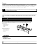
Overview Print quality issues have been identified when printing on tag stock with a thicknesses over 7 mil, or when back feeding small labels shorter than .5" This Printhead Screw and Printhead Mounting Bracket kit has been developed to correct this issue. This document describes the installation of this upgrade kit for the E-Class Mark III printer. After verifying the contents of the kit and the tools needed, follow the steps below to install the upgrade.
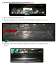
1.) Open the printhead/ribbon carrier assembly by sliding the green button downward (Fig 1) Figure 1 2.
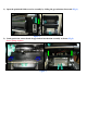
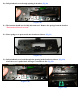
3.) Using needle nose pliers, hold the side of the e-clip in place. Then, using a small flathead screwdriver, gently pry the e-clip outward to remove it (Fig 3) Figure 3 4.) Gently push tabs inward to drop the printhead cover (Fig 4) Do NOT change the media sensor position Figure 4 5.) Remove the printhead screw (Fig 5) The printhead screw will not be re-used.
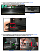
.) Disconnect the printhead cable from the printhead. (Fig 6) Figure 6 7.) Remove the printhead from the printer. 8.) Disconnect printhead cover from the bracket by pushing inward on post (red arrows) and then pulling the printhead cover outward (green arrow). (Fig 8) Figure 8 9.) Lift hinge of the bracket through the opening of the ribbon carrier assembly to unhook. (Fig 9) .
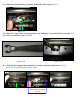
10.) Pull printhead cover through opening in bracket. (Fig 10) (Figure 10) 11.) The bracket should now be fully disconnected. Remove the springs from the bracket. The bracket will not be re-used. 12.) Place springs over posts on the new bracket as shown. (Fig 12) (Figure 12) 13.) Pull printhead cover back through the opening in the bracket as shown. (Fig 13a) After the cover is pulled back through, it should look like Fig 13b.
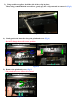
14.) Place the hinge of the bracket in the ribbon carrier assembly as shown (Fig 14a). Hinge should not be visible if fully installed. See Fig 14b. (Figure 14b) (Figure 14a) 15.) Re-install one post of the printhead cover in the bracket opening. (Fig 15) (Figure 15) 16.) Set the remaining post of the printhead cover in the channel and push downward. (Fig 16a) After installed, the printhead cover and bracket, it should look like Fig 16b.
17.) Reconnect the printhead cable to the printhead through the bracket. Figure 17 18.
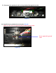
19.) Tighten the printhead screw until the printhead is fully seated (Fig 19) Figure 19 20.) Place the e-clip in the E-Clip Installation Tool, McMaster-Carr part# 5728A2 or similar (Fig 20a) Then, re-install the e-clip. (Fig 20b) Figure 20b Figure 20a 21.
22.) Align the tabs and push up on the printhead mech until it snaps back into place (Fig 22) Figure 22 Tabs should line up as shown 23.) Close the printhead/ribbon carrier assembly. Then, close the printer cover.