92-2448-01 Rev.
Overview This document describes the contents, installation, and use of the I-Class and W-Class GPI/O MultiExpansion option. Additional instructions are included for those using an MCL application. After verifying the contents of your kit and the tools required, follow the steps below to install and use the option. DO NOT remove or change the jumper settings on the circuit card included in this option: equipment damage can occur.
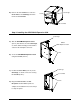
Card Cage B) Remove the two Screws that secure the Cover Plate to the Card Cage, and then Screws remove the Cover Plate. Cover Plate Step 2: Installing the GPI/O Multi-Expansion CCA Card Cage A) Slide the GPI/O Multi-Expansion CCA GPI/O Multi-Expansion CCA (Item ) into leftmost slot of the Card Cage, as shown, and then firmly push the CCA to seat it into the backplane connector. Screws B) Secure the GPI/O Multi-Expansion CCA using two Screws (Item ).
Step 3: Setup and Configuration The GPI/O Multi-Expansion CCA has the following features and can be configured according to your needs (unless otherwise noted, reference the Operator’s Manual for additional setup information, or consult your software package for usage details): Flash Expansion – 8 megabytes of configurable Flash Memory for storage of label formats, fonts, and graphics. (Note that when ILPC Fonts are installed, four Mbytes will remain for other storage uses.
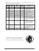
GPIO Port – A General Purpose Input / Output Port for control of printing functions via an external device (e.g., a label applicator), as detailed below: Pin Number Signal Name Signal State Signal Direction * 1 Vcc +5 VDC Output +5 VDC power supply. 2 Ribbon Fault Low Output Goes low when a ribbon out condition is detected. 3 Paper Fault Low Output Goes low when an out of stock condition is detected. 4 Printer Fault Low Output Goes low when any printer fault is detected.
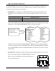
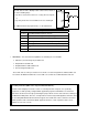
GPIO Start of Print Control External Start of Print / Backup Label control can be made in one of the following ways: By direct connections to Pins 8 & 7 using TTL-level inputs; or, By using an interface circuit similar to the one shown right. For additional interfacing requirements, see the table below. GPIO Specifications* Vin max 5.5 VDC maximum input into any pin VIH 3.8 VDC minimum (high level input voltage) VIL 1.