92-2586-01 Rev.
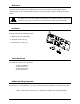
Overview This document describes the installation and use of the General Purpose Input Output (GPIO) option for the I-Class Mark II printer. Follow the steps to begin installing/using the option. For safety and to avoid equipment damage, turn OFF the power switch and CAUTION unplug the AC power cord from the printer before starting this installation. Contents 1 This kit contains the following items: GPIO Circuit Card Assembly Standoff, 6mm Hex (2) Locking Nut, 5.
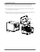
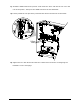
Installing the Option If the GPIO Card is already installed in the printer, skip this section and proceed to “Configuring the Hardware”. Otherwise, install the GPIO Card as described below: A) Turn off and disconnect the power cord from the printer. Remove the three Screws from the left side cover of the printer. B) Open the printer’s cover, loosen (do not remove) the two Screws on the inside of the printer and lift the Cover Assembly up and off the printer.
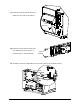
C) Remove the 5mm Screw and Cover Plate from the rear of the printer. Cover Plate 5mm Screw D) Remove the two Jack Screws from the GPIO Card, (these will be reinstalled later in the procedure). Jack Screws E) Install the two 6mm Standoffs into the main board in the locations shown.
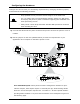
F) Install the GPIO Card into the printer. First insert the “Port” end into the cut-out in the rear of the printer. Then pivot the GPIO Card onto the two Standoffs. G) Loosely install the two previously removed Jack Screws and the two 5.5mm Nuts. Jack Screws 5.5mm Nuts H) Tighten the two Jack Screws and the two 5.5mm Nuts. Proceed to “Configuring the Hardware” on the next page.
Configuring the Hardware Configure the card to meet your interfacing requirements by arranging hardware jumpers, as described in the following procedure: Only qualified service personnel should configure of the GPIO card. For your safety and to avoid equipment damage, always turn OFF power and unplug the printer’s power cord before beginning this installation and when performing service. Always wear a wrist strap and follow standard ESD prevention measures when handling the card.
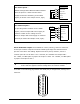
GPI/O A - J1 For direct inputs – 3 Start of Print Default Configuration JMP2 and JMP3 installed. 4 Uses the printer’s +5VDC and Ground to Slew Label 5 Toggle/Pause supply the devices interfacing to the GPIO 6 Reprint inputs (as shown in the sample circuit, right). 1 Ground For isolated inputs – GPI/O A - J1 +5 VDC + External To provide galvanic isolation for the GPIO inputs, remove Jumper JMP 2 then supply an 2 Vcc 3 Start of Print 4 Slew Label external +5VDC source voltage to Pin 2.
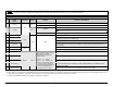
Failure to properly configure the GPIO Port can result in damage to the printer and / or connected devices. WARNING GPI/O Port A Jumper Overview Pin 1 Signal Name Direction Ground [1] Jumper JMP 3 +5 VDC Installed Removed JMP 2 Removed Start Of Print 4 Slew Label 5 Toggle / Pause Reprint 7 +24 VDC 8 Ground 9 Ribbon Low 10 Service Required 11 End Of Print 12 Media Out 13 Ribbon Out 14 Data Ready 15 Option Fault Ground must be supplied. Note: Drawing more than .
Setup and Operation The GPIO card has the following menu configurable features and can be tailored to your application. GPIO PORT GPIO DEVICE Controls the optional Applicator Interface Card’s GPIO function, where: Sets the option to work with a specific device type, where: DISABLED Disables the option. APPLICATOR Enables parameters for related label applicator functions: • Completion upon last SOP, de-asserts Data Ready (DRDY); • FEED allowed at any time; and, • DRDY upon PAUSE.
Test an Diagnostics Input Monitor – Display incoming GPIO binary signal states using the DIAGNOSTICS OPTIONS TESTING TEST GPIO MONITOR GPIO INPUT selection. SOP 1 FEED 1 PAUSE 1 REPRT 1 Note: Unused, non-connected inputs will have an indeterminate state, and may assume a value of 1 or 0. Output Monitor – Display outgoing GPIO binary signal states using the DIAGNOSTICS OPTIONS TESTING TEST GPIO TEST GPIO OUTPUT selection.