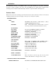
92-2406-01 Rev.
CAUTION This device complies with FCC Radio Frequency exposure limits for an uncontrolled environment. This equipment should be installed and operated with a minimum distance of 20cm between the radiator and your body. If 20cm distance cannot be maintained, end users are to be 20cm from printer extremity. Any changes or modifications to this RFID module not expressly approved by Datamax-O’Neil Corporation will void the user’s authority to operate the equipment.
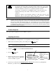
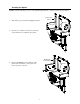
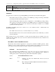
Installing the Option If RFID is already installed, proceed to “Programming Information”; otherwise, follow the steps below: 1. Turn off the power switch and unplug the printer. Front Cover Panel Screws 2. Open the cover. Remove the three Screws that secure the Front Cover Panel to the printer. RFID Front Cover Panel 3. Position the RFID Front Cover Panel on the printer and re-install two of the previously removed screws, as shown.
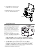
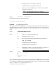
4. Route the RFID Cable, as shown, then connect the cable to the connector in the Centerplate. This completes the installation. Load Smart labels and ribbon (if necessary) then close the printer’s cover. Proceed to “Programming Information.” RFID Cable Centerplate Programming Information Because the RFID device is attached to the cover, the cover must be lowered for all printing applications.
Initialization The initialization interface to the RFID module is auto baud detectable by the printer. Commands necessary to enable, configure, read, write, and verify RFID tags are detailed below, arranged in the following sections: Database / Menu, Data Input, Interfaces, Option Feedback, and Diagnostics.
Data Input Data Input is in the form of System and Label Formatting commands, where KcRI and KcQQQ support the entries that are shown in Menu mode. The RFID database file (RFID_DB) resides on the Y module. It stores RFID information and should not be deleted. If not found at power-up then factory defaults will be set.
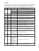
KcOFa configures the printer to output the status of the RFID operation, as noted below: Value D, Rx, S Range / Interpretation D - Disable R - RFID Enable, where x = A - ASCII Response, x = H - Hexadecimal response S - Scanner Enable Interfaces The printer has two methods of programming RFID tags: Direct Mode and Label Formatting Mode. Direct Mode allows the Host to directly control RFID tag reading and writing, individually processing each with status and data responses.
c - Command 1. Reserved for Future (should be 0) d - Command 2. Reserved for Future (should be 0) ee…e - Data to be encoded on RFID tag (HF – the last used block will be null-padded, if necessary). Note: UHF ASCII formats must be 8 or 12 characters. UHF Hexadecimal formats must be 16 or 24 character pairs. Sample: KaW0000054455354[CR] The sample writes the data “TEST” at block zero. * Dependent on transponder manufacturer.
Direct Mode - HF (13.56 MHz) ISO15693 Tag Interface This interface allows the Host Application to perform specific operations pertaining to HF type tags. These commands override the printer database as they interface directly to the tag module. Knowledge of HF tags and their operation is required. STX KtW Write Data to RFID Tag This command instructs the RFID device to write data to the tag.
STX KtR Read Data from RFID Tag This command instructs the RFID device to read data from the tag and then put that data into a replaceable field. It is expected that the tag transponder will be within the read / write distance of the RFID programming device; otherwise, “Void” will be printed in the text or bar code label field(s). Syntax: KtRUn1…n16Haaabbbcdee Where: Un1…n16 - (Optional) Where n1…n16 is the Unique Identifier (UID) in hexadecimal format. Must be sixteen characters long.
STX KtU Read Unique Serial Number from RFID Tag This command instructs the RFID device to read the unique serial number data from the tag and then place that data into a replaceable field. It is expected that the tag transponder will be within the read / write distance of the RFID programming device; otherwise, “Void” will be printed in the text or bar code label field(s). Note: This is a sixteen character alphanumeric value; therefore, the replaceable field must have an adequate length.
STX KtD Write Data Storage Format Identifier (DSFID) to Tag This command writes the DSFID data to the tag. Syntax: KtDabcc Where: a - The number of retry attempts, 0-9. b - Lock the Data Storage Format Identifier (DSFID) after writing: 0 = No Protection 1 = Write Protect cc - Two character DFSID value representing one byte. KtD91C3[CR] Sample: The sample writes 0xC3 DSFID byte, locking value, retrying nine times, if necessary.
Direct Mode- UHF Interface This interface allows the Host Application to perform specific operations pertaining to UHF type tags. These commands override the printer database as they interface directly to the tag module. Knowledge of UHF protocols and their operation is required. STX KuW Write Data to RFID Tag This command instructs the RFID device to write data to the tag.
STX KuE Erase RFID Tag (Alien only) This command erases the tag by filling it with nulls (0x00). Syntax: KuEa Where: a STX KuL - The number of attempts to locate and erase the tag, 1-9. Lock RFID Tag (Alien only) This command locks tag. Syntax: KuLabb Where: a - The number of attempts to locate and lock the tag, 1-9. bb - Two character Lock Code value, representing one byte. STX KuB Read Data from Gen2 Tag Section This command reads a specific block address of a Gen2 tag.
STX KuJ Write Data to Gen 2 Tag Section This command writes a specific block address of a Gen2 tag.
STX KuT Send Tag ID (Alien only) This command instructs the RFID device to read data from the tag and return it to the host. This is a low level command that issues an air interface command to acquire one tag ID. There is no collision avoidance used. A CRC validation is performed on the data; however, the CRC data is not returned.
Label Formatting Mode As mentioned earlier, Label Formatting mode utilizes the current printer configuration to process each tag printed. (For exception processing and fault handling, see the KcFH command.) The specification for RFID programming is contained in the data fields of the DPL label format, as described below.
WX / W1X: RFID with Byte Count Specifier The upper case X identifies an RFID data string with a string 4-digit length specifier, which allows values 0x00 through 0xFF to be included within the data strings without conflicting with the DPL format record terminators. The four-digit decimal data byte count immediately follows the four-digit column position field. This value includes all of the data following the byte count field, but does not include itself.
Option Feedback Once enabled, the printer will report information about the results of the last label printed. One response per label is returned to the host (this includes each voided and retried label).
Diagnostics Menu mode accesses testing functions. Press the Menu Key and scroll to DIAGNOSTICS / OPTIONS TESTING / TEST RFID. Note: Upon selection, NOT INSTALLED will be displayed if the device is not equipped or communicating. In this case, verify the Mode selection. TAG DATA – Acts as an RFID reader and will read and display data from block zero through ten for HF, or the entire tag for UHF. If the tag cannot be found after 10 tries, CANNOT READ RFID TAG will be displayed.